Thrombus removal apparatus

a technology for removing thrombosis and thrombosis, which is applied in the field of thrombosis apparatus, can solve the problems of not being able to readily aspirate into a catheter, thrombosis material is not generally dissolving readily, and thrombosis material is not normally able to be removed. it can be made very compact

Active Publication Date: 2017-04-25
COOK MEDICAL TECH LLC
View PDF14 Cites 4 Cited by
  • Summary
  • Abstract
  • Description
  • Claims
  • Application Information

AI Technical Summary

Benefits of technology

[0011]Preferably, the coil is made from flat strip material. In an embodiment, the coil is wound in helical manner around a substrate forming a layer of the coil section or catheter. The coil may be would in a plurality of layers, in which case the coil may be provided with insulation to prevent electrical shorting between overlapping layers.
[0022]The structure and method disclosed herein provide a device which is able to pierce into a thrombus and cause this to fragment. The piercing element can be made to reciprocate so as to strike the thrombus material repeatedly, thereby contributing to the destruction of the thrombus and its removal. The device can be made very compact and is able to be used in cerebral applications.

Problems solved by technology

Existing methods are generally successful in removing many types of thrombi but are not normally able to remove thrombi formed of denser material, such as found in older thrombus formations.
Such thrombus material does not generally dissolve readily with thrombolytic drugs at physiologically safe concentrations and cannot readily be aspirated into a catheter.
Moreover, such thrombi tend to be attached to the vessel wall, with the result that filtration is an ineffective tool for removing them.

Method used


Image

  • Thrombus removal apparatus
  • Thrombus removal apparatus
  • Thrombus removal apparatus

Examples


Embodiment Construction

[0029]It is to be understood that the drawings are schematic only and not to scale.

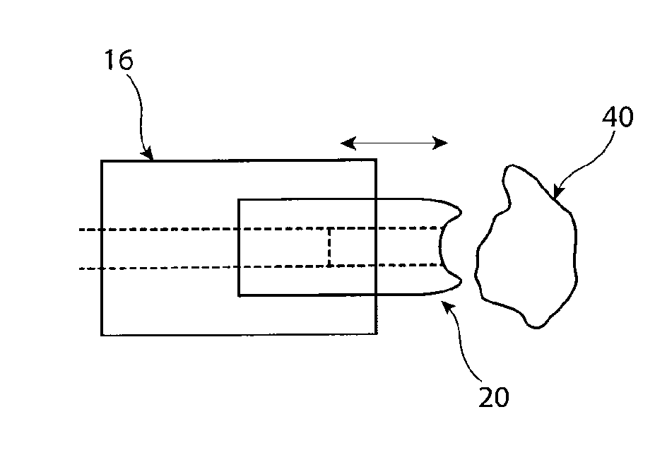
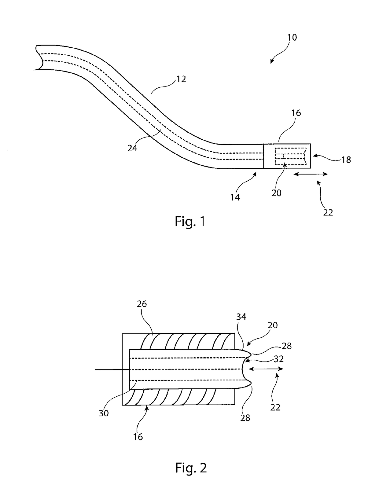
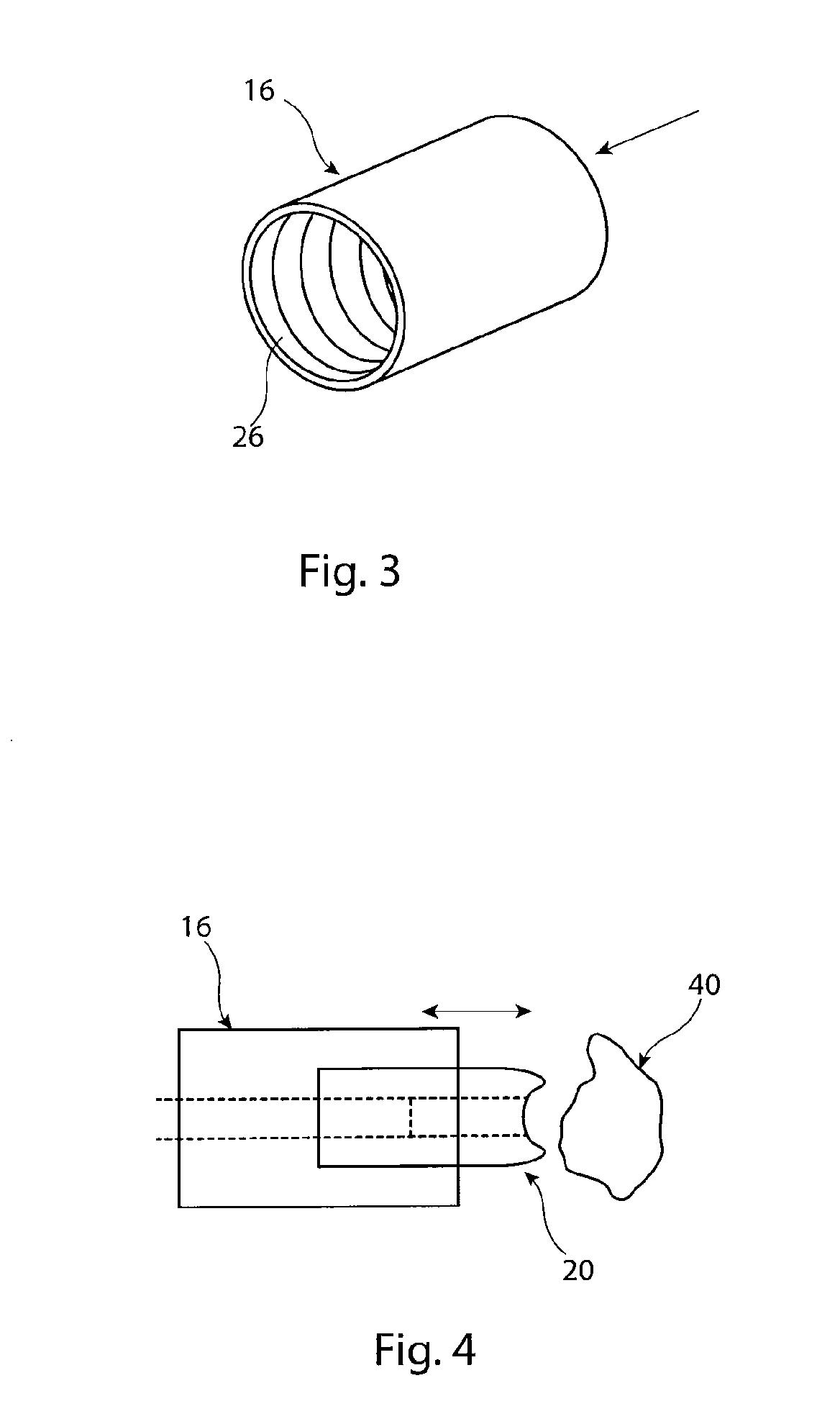
[0030]The embodiments of thrombus removal device described herein are in the form of a catheter or sheath (hereinafter referred to generically as a catheter) having a piercing element disposed in the catheter and reciprocally movable within the catheter. The piercing element is moved to extend beyond the distal end of the catheter, so as to strike and cut into a thrombus to cause the latter to fragment. The assembly is able to manufactured with a very small footprint, that is a very small outer diameter, and to be very flexible, enabling the assembly to be used in narrow vessels including cerebral vessels. It will be appreciated the device can also be used for larger vessels and thus manufactured to have a larger diameter.

[0031]As will be apparent from the description of the preferred embodiments given below, the apparatus disclosed herein is particularly useful in the removal of established thrombi a...


PUM


Abstract

A thrombus removal apparatus (10) includes a catheter (12) having at its distal end (14) a solenoid coil section (16) within which there is disposed a piercing element (20) made of electromagnetic material. Within the solenoid coil section (16) there is provided a solenoid coil (26) which can be powered to generate an electromagnetic field which causes the piercing element (20) to reciprocate into and out of the coil section (16), in practice to pierce into and fragment a thrombus disposed in a patient's vessel. An aspiration unit may be provided for aspirating thrombus fragments into the assembly (10) for removal from the patient's vasculature. The apparatus (10) is able to remove dense thrombus material from within a patient, which cannot be otherwise removed by means of thrombolytic agents.

Description

[0001]This application claims the benefit of the filing date of United Kingdom (GB) patent application number 1301428.7, filed Jan. 28, 2013, which is hereby incorporated by reference herein.TECHNICAL FIELD[0002]The present invention relates to apparatus for removing thrombi from a patient's vasculature.BACKGROUND ART[0003]There are many systems for treating and removing thrombi from a patient. Traditional methods involve the administration of blood thinning medicaments (thrombolytic agents) which are intended to dissolve thrombus material, which can then be dispersed in the blood stream. Other systems use filters for capturing thrombus material, which can then either be removed along with the filter or dissolved with appropriate medicaments. Yet other systems involve aspiration of thrombus material through a retrieval catheter.[0004]Existing methods are generally successful in removing many types of thrombi but are not normally able to remove thrombi formed of denser material, such...

Claims


Application Information

Patent Timeline
Patent Type & Authority Patents(United States)
IPC IPC(8): A61B17/3207A61B17/22A61B17/00A61B17/32
CPCA61B17/320758A61B17/22012A61B17/3207A61B2017/00398A61B2017/00415A61B2017/22021A61B2017/320028
Inventor ANDERSEN, TORBEN PETER
Owner COOK MEDICAL TECH LLC
Why Eureka
Try Eureka