Lens driving unit, and a camera module and an optical appliance including the same

a technology of driving unit and camera module, which is applied in the direction of television system, printing, instruments, etc., can solve the problems of deteriorating the quality of the camera module, increasing the height of the entire product, and increasing manufacturing costs

Active Publication Date: 2018-09-25
LG INNOTEK CO LTD
View PDF18 Cites 16 Cited by
  • Summary
  • Abstract
  • Description
  • Claims
  • Application Information

AI Technical Summary

Benefits of technology

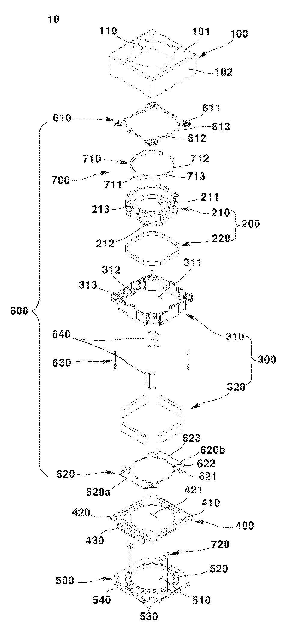
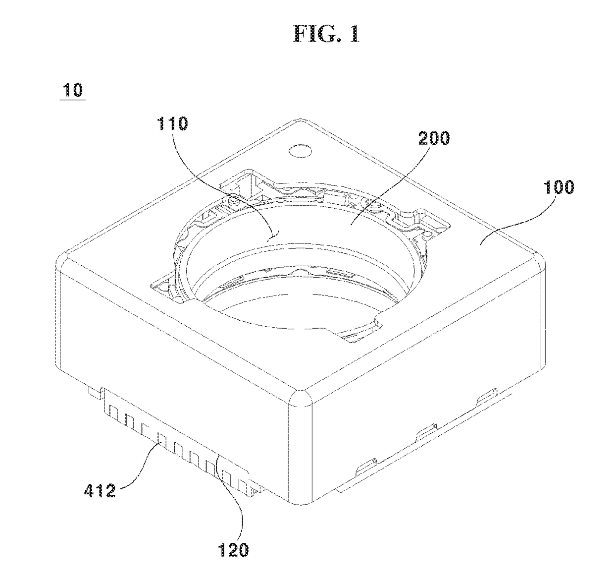
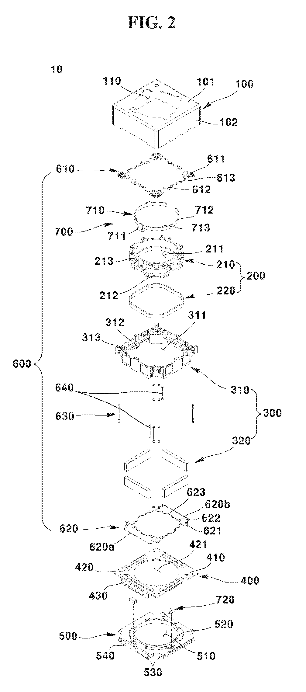
[0017]Embodiments provide a lens driving unit, which achieves a reduction in the number of elements, the number of processes, the number of process management points, and the height of an entire product.

Problems solved by technology

Conventional camera modules have a high price and a large number of manufacturing processes due to the great number of elements thereof, and an increase in process management points upon the manufacture of a product results in increased manufacturing costs and an increased height of the entire product.
In addition, because a printed circuit board and a circuit member have different sizes, the printed circuit board may be warped when the circuit member is assembled to one surface of the printed circuit board, which deteriorates the quality of the camera module.
In addition, a gap may be generated between a pad unit provided on one surface of the printed circuit board and a base to which the printed circuit board is assembled, thus causing contact failure.
In addition, when only the pad unit is provided on one surface of the printed circuit board, a portion of a pad may be separated from the printed circuit board during soldering, which causes deterioration in the quality of the camera module.
When the base, the printed circuit board, and the circuit member are sequentially assembled with one another, the circuit member does not come into contact with the base, which may make the height of the circuit member uneven.
In addition, when a pattern, which protrudes from the pad provided on one surface of the printed circuit board, is thin, the pad may be cracked by an external shock.
When the circuit member is tilted, rather than being evenly disposed on the upper surface of the printed circuit board, the resolution of the camera module may be deteriorated.
In addition, because a conventional lens driving apparatus is configured such that the circuit member and the printed circuit board are assembled with each other, rather than integrally forming the circuit member and the printed circuit board, a foreign substance may be introduced between the circuit member and the printed circuit board, thus causing deterioration in the resolution of the camera module.

Method used


Image

  • Lens driving unit, and a camera module and an optical appliance including the same
  • Lens driving unit, and a camera module and an optical appliance including the same
  • Lens driving unit, and a camera module and an optical appliance including the same

Examples


Embodiment Construction

[0089]Hereinafter, some embodiments will be clearly revealed via description thereof with reference to the accompanying drawings. Wherever possible, the same reference numbers will be used throughout the drawings to refer to the same or like parts. In addition, in the following description of the embodiments, a detailed description of known functions and configurations incorporated herein will be omitted when it may impede the understanding of the embodiments.

[0090]In addition, in the description of constituent elements of the embodiments, terms “first”, “second”, “A”, “B”, “(a)”, “(b)”, and the like may be used to distinguish any one element from another element without requiring or containing any physical or logical relationship or sequence between these substances or elements. When an element is described as being “connected” or “coupled”, to another element, it can be directly connected or coupled to the other element, or intervening elements may also be “connected” or “coupled”...


PUM

PropertyMeasurementUnit
angleaaaaaaaaaa
lengthaaaaaaaaaa
distanceaaaaaaaaaa

Abstract

Embodiments provide a lens driving unit including a base, a housing supported so as to be movable relative to the base, a magnet located on the housing, a pattern coil part including a pattern coil that is located opposite the magnet, the pattern coil part being located on the base, and a sensor part mounted to the pattern coil part for sensing a position or movement of the housing, and the pattern coil part includes a first layer and a second layer stacked on the first layer, the sensor part being mounted underneath the first layer, and the pattern coil being formed on the second layer. Thereby, manufacturing costs may be reduced owing to a reduction in the number of elements, processes, and process management points.

Description

CROSS REFERENCE TO RELATED APPLICATION[0001]This application claims priority under 35 U.S.C. § 119 to Korean Patent Application Nos. 10-2015-0133180, filed Sep. 21, 2015; 10-2015-0135403 and 10-2015-0135404, filed Sep. 24, 2015, which are hereby incorporated by reference in their entirety.TECHNICAL FIELD[0002]Embodiments relate to a lens driving unit, a camera module, and an optical appliance.BACKGROUND[0003]The following disclosure merely provides background information related to the embodiments and does not describe the related art.[0004]As various kinds of portable terminals have become widely generalized and popularized and wireless Internet service is commercialized, consumer demand related to portable terminals has been diversified, and therefore various kinds of additional devices have been mounted to portable terminals.[0005]A representative one of these additional devices is a camera module that captures a still or moving image of an object.[0006]Recent camera modules incl...

Claims


Application Information

Patent Timeline
Patent Type & Authority Patents(United States)
IPC IPC(8): H04N5/232H04N5/225G02B27/64H01F7/06G02B7/08G03B13/00
CPCG02B7/08G02B27/646H01F7/064H04N5/23287H04N5/2257H04N5/23212H04N5/2253G02B7/09G03B13/36G03B5/00H04N23/50H04N23/54H04N23/57H04N23/67H04N23/687
Inventor PARK, TAE BONGLEE, SUNG GUK
Owner LG INNOTEK CO LTD
Why Eureka
Try Eureka