
Plug connector assembly having improved arrangement structure between outer case and printed circuit board

a technology of connectors and printed circuit boards, which is applied in the direction of electrical equipment, basic electric elements, coupling device connections, etc., can solve the problems that the side walls of the connectors may be difficult to cover the side edges of the intermediate portion of the printed circuit boards, and achieve the effect of improving the arrangement structur

Active Publication Date: 2018-09-25
FOXCONN INTERCONNECT TECH LTD
View PDF16 Cites 7 Cited by
  • Summary
  • Abstract
  • Description
  • Claims
  • Application Information

AI Technical Summary

Benefits of technology

Ensures complete enclosure of the printed circuit board's side edges by the outer case, enhancing the structural integrity and electrical performance by improving the over molding process and reducing exposure risks.

Problems solved by technology

The size of the intermediate portion is same as the mating end such that if the outer case is formed by over molding, the side wall thereof may be difficult to cover the side edges of the intermediate portion of the printed circuit board.

Method used


Image

  • Plug connector assembly having improved arrangement structure between outer case and printed circuit board
  • Plug connector assembly having improved arrangement structure between outer case and printed circuit board
  • Plug connector assembly having improved arrangement structure between outer case and printed circuit board

Examples


Embodiment Construction

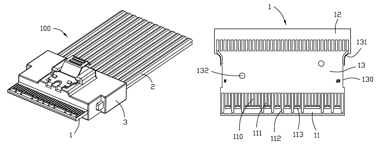
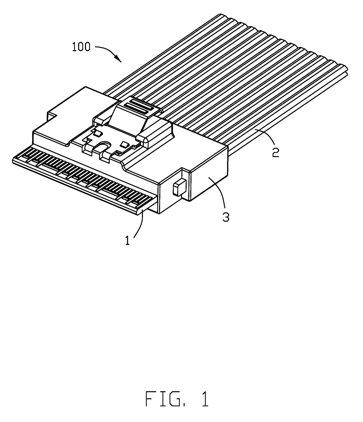
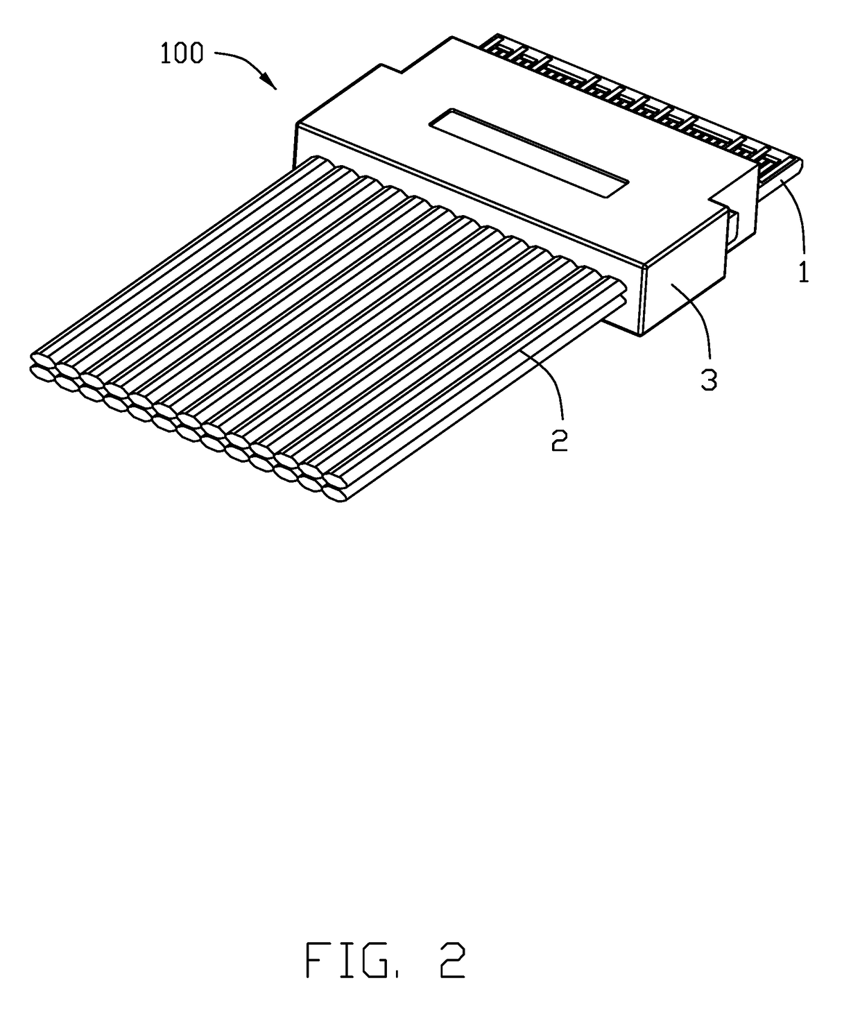
[0012]Referring to FIGS. 1 to 6, a plug connector assembly in accordance with the present invention for mating with a mating connector (not shown), comprises a printed circuit board 1, a cable 2 electrically connected with the printed circuit board 1, an outer case 3 enclosing the printed circuit board 1 and the cable 2. In the present embodiment, the plug connector assembly 100 conforms to the SFF-8654 specification with a transmission rate of more than 22.5 Gbps per channel. The cable 2 is a flat structure comprising a plurality of core wires 21.

[0013]The printed circuit board 1 includes a mating end 11 for being inserted into the mating connector, a connecting end 12 connecting with the cable 2, a intermediate portion 13 connecting between the mating end 11 and the connecting end 12. The printed circuit board 1 defines a top surface 101 and an opposite bottom surface 102.

[0014]The mating end 11 defines a plurality of mating conductive pads 110 extending along a longitudinal direc...


PUM


Abstract

A plug connector assembly includes: a cable; a printed circuit board including a mating end for inserting into a mating connector, a connecting end electrically connected with the cable, and an intermediate portion between the mating end and the connecting end, the mating end defining plural conductive pads extending along a longitudinal direction of the printed circuit board for electrically connecting with the mating connector and arranged in a horizontal direction perpendicular to the longitudinal direction; and an outer case enclosing the intermediate portion of the printed circuit board and a part of the cable; wherein the intermediate portion defines on each of two side edges thereof a recessing portion filled by the outer case.

Description

BACKGROUND OF THE INVENTION1. Field of the Invention[0001]The present invention relates generally to a plug connector assembly and more particularly to an improved arrangement structure between outer case and printed circuit board.2. Description of Related Arts[0002]China Patent Application Publication No. 203574938, issued on Apr. 30, 2014, shows a plug connector assembly including a printed circuit board, a cable electrically connected with the printed circuit board, and an outer case. The printed circuit board includes a mating end, a connecting end connecting with the cable, and an intermediate portion between the mating end and the connecting end. The size of the intermediate portion is same as the mating end such that if the outer case is formed by over molding, the side wall thereof may be difficult to cover the side edges of the intermediate portion of the printed circuit board.[0003]An improved arrangement structure in a plug connector assembly is desired.SUMMARY OF THE INV...

Claims


Application Information

Patent Timeline
Patent Type & Authority Patents(United States)
IPC IPC(8): H01R24/60H01R13/62H01R107/00
CPCH01R24/60H01R13/62H01R2107/00H01R13/46H01R13/665H01R12/59H01R13/6658
Inventor XING, DA-WEICHEN, JUNWU, JERRY
Owner FOXCONN INTERCONNECT TECH LTD
Learn More