
Method for controlling a compressor

a compressor and compressor element technology, applied in the direction of machines/engines, mechanical equipment, radial flow pumps, etc., can solve the problems of relatively high complexity and production costs, typically reduced pressure of the compressor element, and high energy consumption, so as to reduce the inlet pressure and energy consumption. , the effect of less energy

Active Publication Date: 2018-10-02
ATLAS COPCO AIRPOWER NV
View PDF37 Cites 2 Cited by
  • Summary
  • Abstract
  • Description
  • Claims
  • Application Information

AI Technical Summary

Benefits of technology

The patent describes a method for controlling the pressure of air in a compressor system. By reducing the inlet pressure of the compressor, it is possible to maintain a certain speed for a longer period of time, which requires less energy to transfer to full load. This allows for more efficient and accurate control of the air pressure, even when there are changes in demand. This method is particularly useful when the motor torque is limited.

Problems solved by technology

In such a case the inlet pressure of the compressor element is typically reduced at constant speed (however, the foregoing is not the case if the compressor element is constructed according to the turbo type).
An important disadvantage of the known methods consists of them being energy intensive.
A disadvantage of this is the relatively high complexity and production costs attached to this.
A disadvantage of this, however, is that significant losses arise in the transition between the loaded and unloaded states and vice versa, because the power of the centrifugal compressor is not very dependent on the final pressure.

Method used


Image

  • Method for controlling a compressor
  • Method for controlling a compressor
  • Method for controlling a compressor

Examples


Embodiment Construction

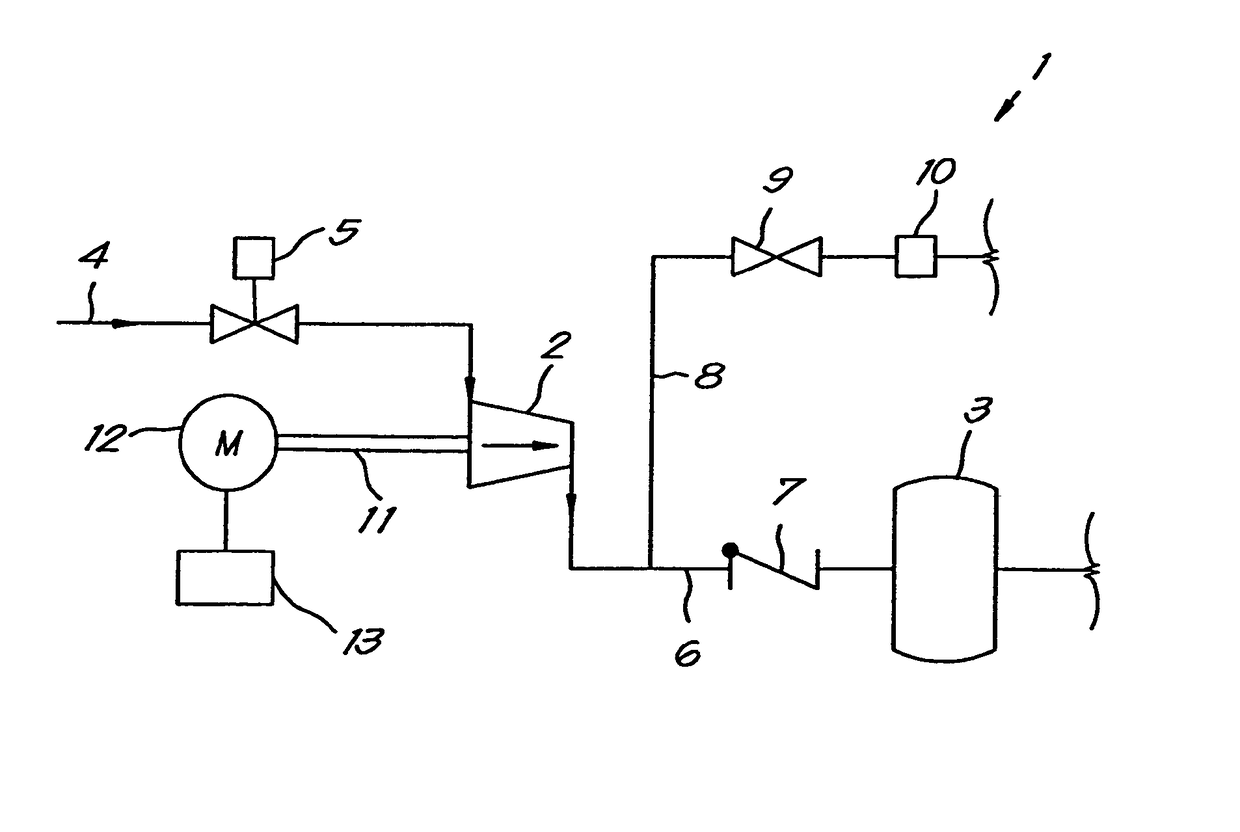
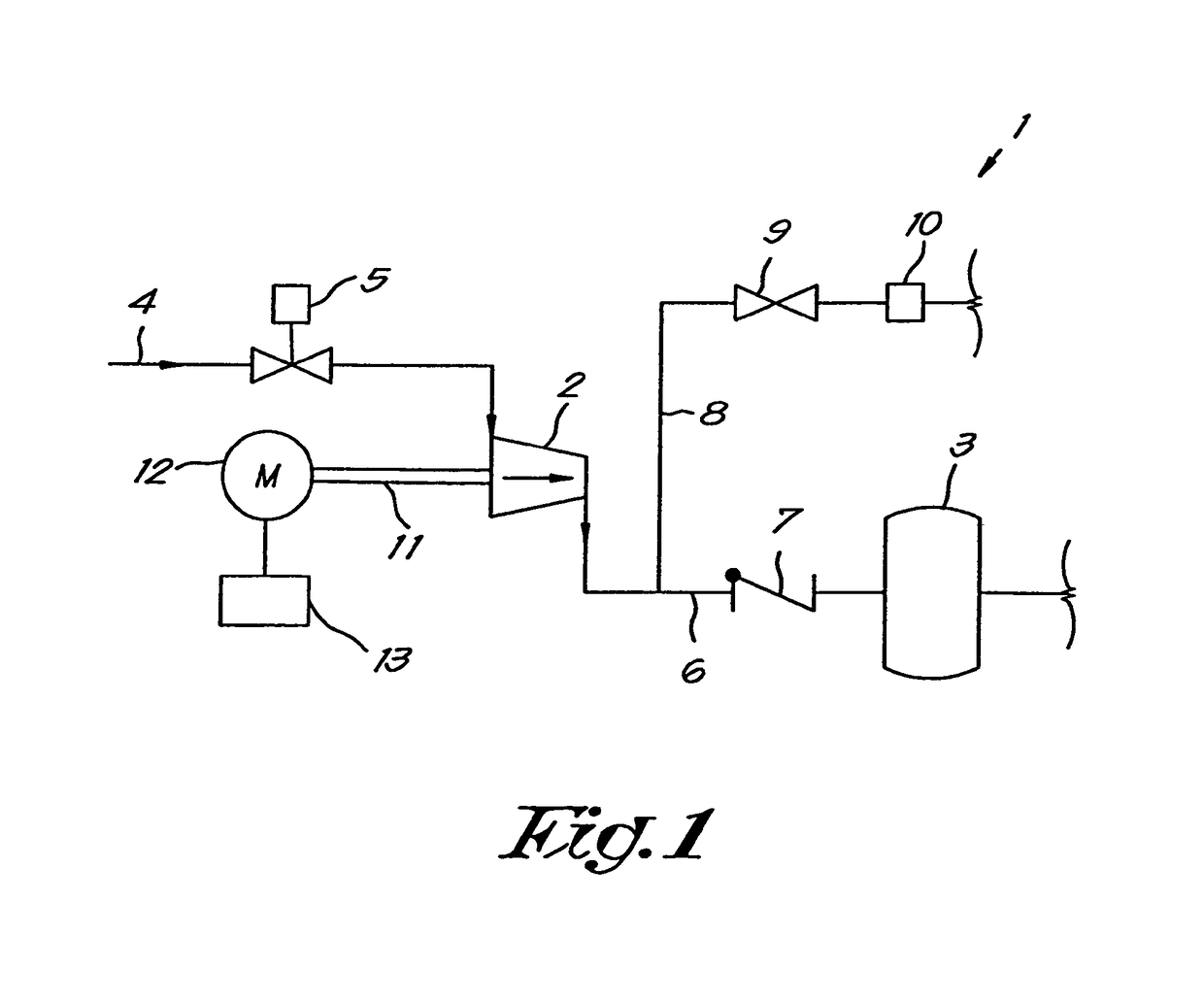
[0034]FIG. 1 shows a compressor 1 which, in this non-limiting example, only contains one compressor element 2, in this case of the turbo type, and this compressor element supplies compressed gas to a pressure network 3, to which one or more compressed gas users are connected.

[0035]An inlet pipe on the intake side of the compressor element 2 has an inlet valve 5 and is connected to the inlet for the gas to be compressed of the compressor element 2.

[0036]The inlet valve 5 in this case is, but not necessarily so, constructed such that, even in the fully closed state, it allows a certain minimum gas flow through to the compressor element 2. Such an inlet valve 5 can, according to a variant not shown in the drawings, for example but not necessarily so, be realised by constructing the inlet valve 5 in the form of a shut-off valve across which there is a bypass pipe that, in the fully closed state of the shut-off valve, allows a flow across this shut-off valve. Alternatively such an inlet ...


PUM


Abstract

A method for controlling a compressor that includes a compressor element, whereby during a transition from full load or partial load to zero load, a process A is followed that involves: (1) reducing the inlet pressure; and (2) reducing the speed and / or the drive torque. During a transition from zero load to part load or full load, a process B is followed that involves: (3) increasing of the speed or drive; and (4) increasing the inlet pressure.

Description

BACKGROUND OF THE INVENTIONA. Field of the Invention[0001]The present invention relates to a method for controlling a compressor that has one or more compressor elements, whereby each compressor element is equipped with an inlet and an outlet, and whereby the compressor can be connected to a load that makes use of compressed gas.B. Related Art[0002]More specifically, the invention is intended for saving energy when going from full load or part load to zero load or vice versa, whereby the compressor contains a control unit that controls the speed of the aforementioned compressor element or the aforementioned compressor elements at nominal speed, or within a certain nominal speed range.[0003]In many cases it is desirable for the flow of the compressed gas at the compressor outlet to be controllable to a certain extent, for example if the compressor supplies a pressure network with compressed gas. In such a situation the gas flow supplied is preferably adjusted according to the consump...

Claims


Application Information

Patent Timeline
Patent Type & Authority Patents(United States)
IPC IPC(8): F04D27/02F04D17/12
CPCF04D27/0261F04D27/0284F04D17/12Y02B30/70F04D27/0215F05D2210/12Y10S415/00Y10S417/00
Inventor HUBERLAND, FILIP GUSTAAF M.PAHNER, UWEBEYENS, FILIP PETRUS IJANSSENS, STIJN JOZEF RITA JOHANNA
Owner ATLAS COPCO AIRPOWER NV
Learn More