
Active vibration damping system of a rolling mill

a technology of vibration damping and active vibration, which is applied in the direction of rolling mill control devices, measuring devices, manufacturing tools, etc., can solve the problems of insufficient rolling process, limited configuration force, waste of rolled strips, etc., and achieves the effect of improving the hydraulic system response and more rapid and effective respons

Active Publication Date: 2018-10-09
DANIELI & C OFF MEC SPA
View PDF6 Cites 0 Cited by
  • Summary
  • Abstract
  • Description
  • Claims
  • Application Information

AI Technical Summary

Benefits of technology

[0037]It is an object of the present invention to provide an active damping system for the resonance vibrations of a cold rolling mill, which is simple and easily feasible, while maintaining high effectiveness.
[0038]It is a further object of the present invention to provide an active damping system for the resonance vibrations of a cold rolling mill, which is alternative and improving compared to the known art, which ensures a higher overall simplicity and small size.
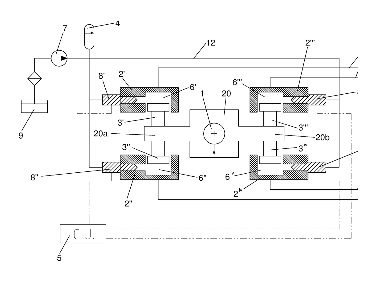
[0046]The injectors, which are preferably of the piezoelectric type for obtaining a more rapid and effective response in damping the vibrations occurring in a rolling stand for the cold rolling of strips, are advantageously directly arranged within the body or in direct proximity of the hydraulic actuators in order o improve the hydraulic system response even more.
[0047]Moreover, the damping system of the invention is exclusively an active damping system because energy is additionally introduced into the hydraulic system through the injectors. Therefore, the damping system of the invention acts in a dynamic manner, exerting some forcings to the hydraulic system, by injecting new fluid into the hydraulic system. The damping system conveniently applies a force by injecting new oil as a function of the roll displacement speed, for making the hydraulic system stable. In essence, the active damping system of the invention applies a force opposite to the force of the vibration, whereby a new disturbance is introduced into the hydraulic system which cancels the disturbance created by the vibration.

Problems solved by technology

Such a configuration is limited in the forces applicable for the elastic deformation of the rolls themselves.
Such forcings may be generated by:the strip itself, due to its intrinsic thickness or hardness variations;friction variations within the rolling room, especially when reaching the limit speed resulting in the—even temporary—breakage of the lubricating film;flaws induced in the working rolls during grinding operations;inadequate conditions of the stand mechanics, such as wears, clearances between various components and damaged rolling bearings;concurrently rolling hard material along with a strong thickness reduction and high rolling speed.
Such phenomena occur with a movement of the rolls, transversally to the rolling direction, i.e. occur vertically and may reach widths which cannot be controlled and are not adequate to the rolling process.
Such phenomena are known as chattering and may generate surface defects, such as light / dark strip markings or thickness variations resulting in the wasting of the rolled strip, the flaws depending on how the stand vibrates.
Chattering is therefore a significant problem affecting the operativeness of rolling mills because, besides causing the wasting of the product, significantly reduces its production capacity.
Such systems allow to minimize the qualitative drop, but do not solve the problem related to the reduction in the rolling plant production capacity.
The technical teaching of this document is to avoid using active vibration damping systems since the energy additionally introduced into the hydraulic system, through the actuator, importantly worsens the whole system stability, and may result in a spoilage in the response of the system.

Method used


Image

  • Active vibration damping system of a rolling mill
  • Active vibration damping system of a rolling mill
  • Active vibration damping system of a rolling mill

Examples


Embodiment Construction

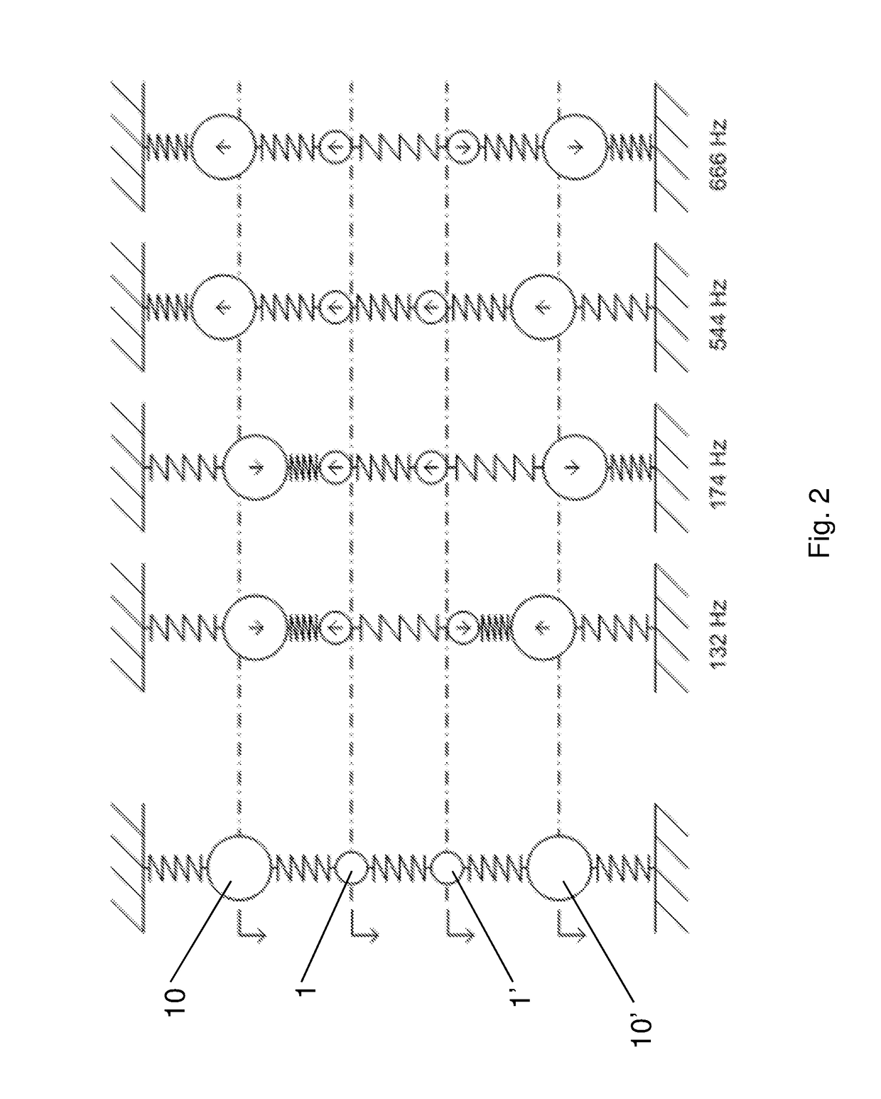
[0060]With reference to a stand of the type in FIG. 2, a simplified dynamic model of a rolling stand for strips is shown. Typical vibration modes of the stand at different frequency values are shown therein: particularly, in that example, the vibration modes are obtained for frequencies of 132, 174, 544, 666 Hz which depend on the dimensional and elastic features of the stand under examination. Therefore, as the bulk, elastic rigidity and damping parameters vary, the natural resonance frequencies change, being known that each rolling stand has its own resonance frequencies.

[0061]Due to the active damping of the present invention, irrespective of transient or stationary conditions generating the instability, the forcing Fv is cancelled due to the opposite damping Fs.

[0062]FIG. 3 shows an example of the third-octave resonant vibration when the active damping system of the invention is disabled or is not provided. Specifically, in the upper graph in FIG. 3, there is shown a strip thick...


PUM

PropertyMeasurementUnit
cut-off frequenciesaaaaaaaaaa
frequenciesaaaaaaaaaa

Abstract

The active vibration damping system of a rolling mill comprises a rolling stand and an adjustment system for the bending of the rolling rolls (1, 1′) having hydraulic actuators (2\2″, 2″′, 2iv) acting on the chock (20) of the rolling rolls (1, 1′) and hydraulic feeding circuits (7, 9, 11, 12) and injectors (8′, 8″, 8″′, 8iv), preferably piezoelectric injectors, directly inserted into the chambers (6\6″, 6″′, 6iv) of the hydraulic actuators (2′, 2″, 2″′, 2iv) with the advantage of exploiting the dampening effect resulting from the high- pressure oil injection.

Description

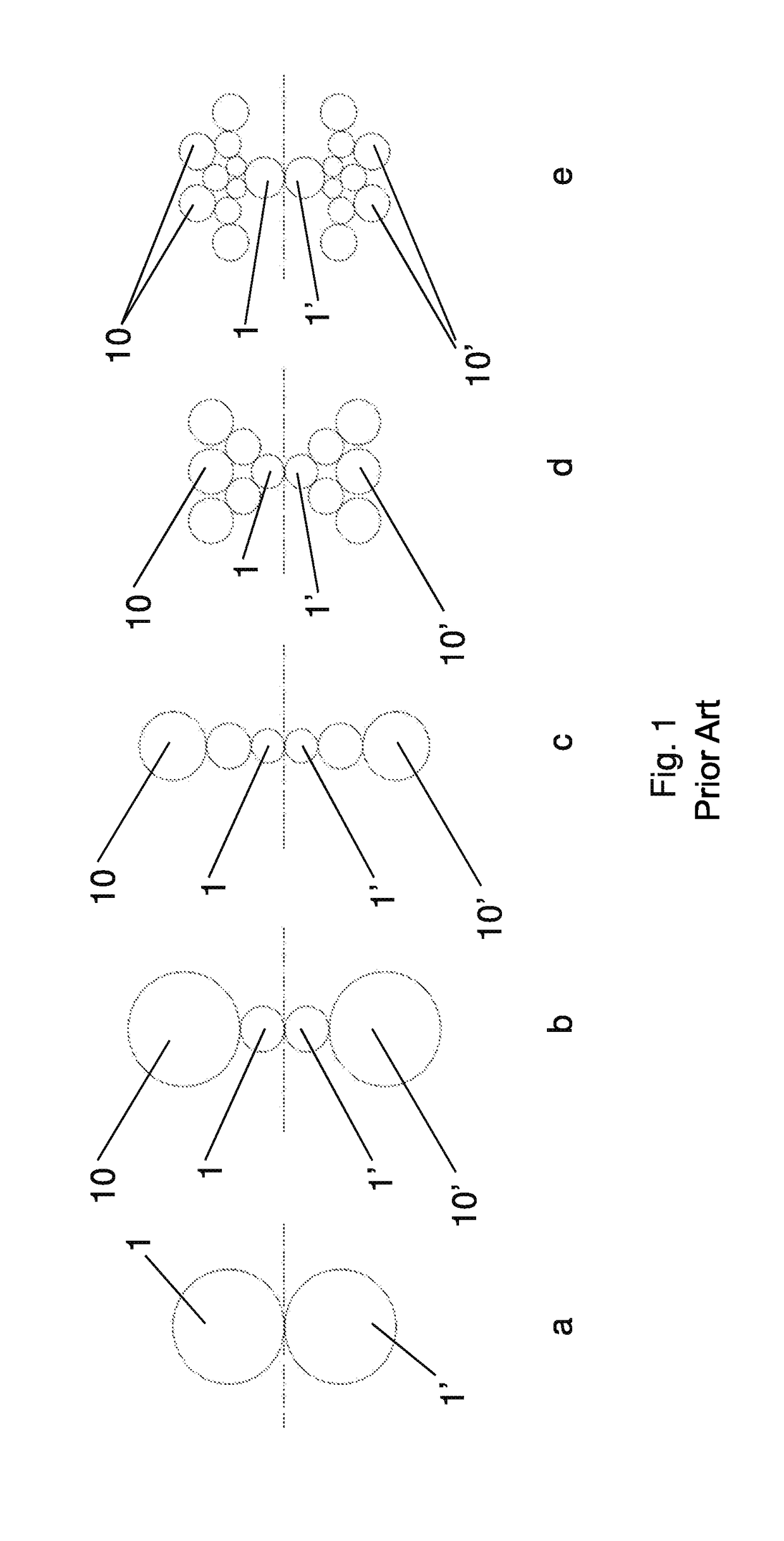
CROSS REFERENCE TO RELATED APPLICATIONS[0001]The present application claims priority to PCT International Application No. PCT / IB2014 / 067214 filed on Dec. 22, 2014, which application claims priority to Italian Patent Application No. MI2013A002170 filed Dec. 20, 2013, the entirety of the disclosures of which are expressly incorporated herein by reference.STATEMENT RE: FEDERALLY SPONSORED RESEARCH / DEVELOPMENT[0002]Not Applicable.FIELD OF THE INVENTION[0003]The present invention relates to a damping vibration system of a rolling stand, particularly for the cold rolling of strips.BACKGROUND ART[0004]Rolling stands comprising, as shown in FIG. 1, at least one pair of working or rolling rolls or cylinders 1, 1′ which are directly in contact with the strip during the rolling process, are used for the cold rolling of strips. One of the two working rolls vertically overlaps the other.[0005]Such a configuration is limited in the forces applicable for the elastic deformation of the rolls themse...

Claims


Application Information

Patent Timeline
Patent Type & Authority Patents(United States)
IPC IPC(8): B21B37/00B21B38/00
CPCB21B38/008B21B37/007B21B31/02B21B2203/44
Inventor DEL TEDESCO, STEFANODE LUCA, ANDREA
Owner DANIELI & C OFF MEC SPA
Learn More