Battery management system and method for managing isolation and bypass of battery cells
a battery cell and management system technology, applied in the field of battery management, can solve the problems of increasing weight and cost, increasing in weight and cost, and constant and heavy load on the working environment of the battery, so as to reduce the spike of high inrush current and reduce the performance of the battery
- Summary
- Abstract
- Description
- Claims
- Application Information
AI Technical Summary
Benefits of technology
Problems solved by technology
Method used
Image
Examples
second embodiment
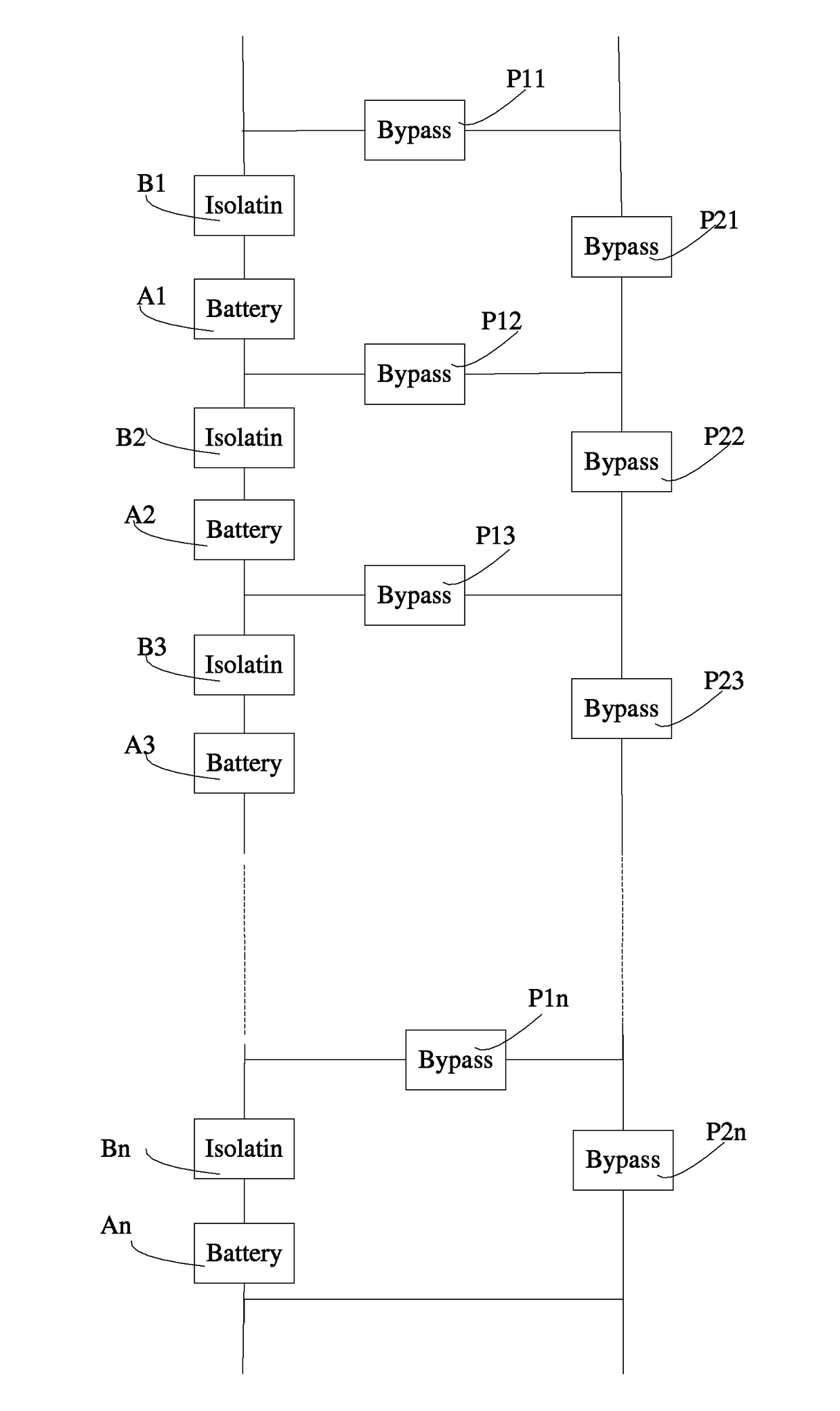
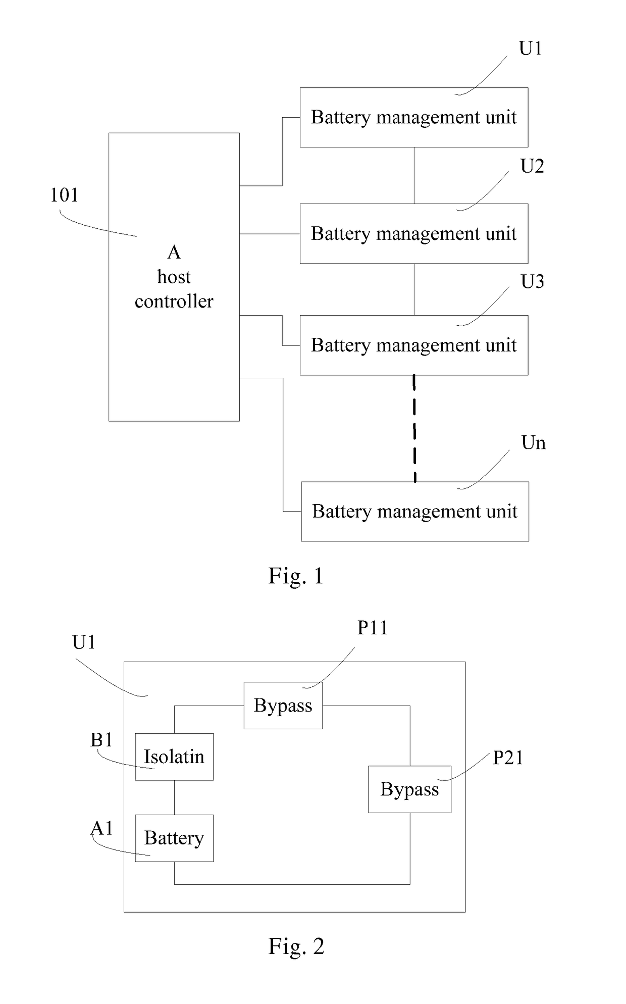
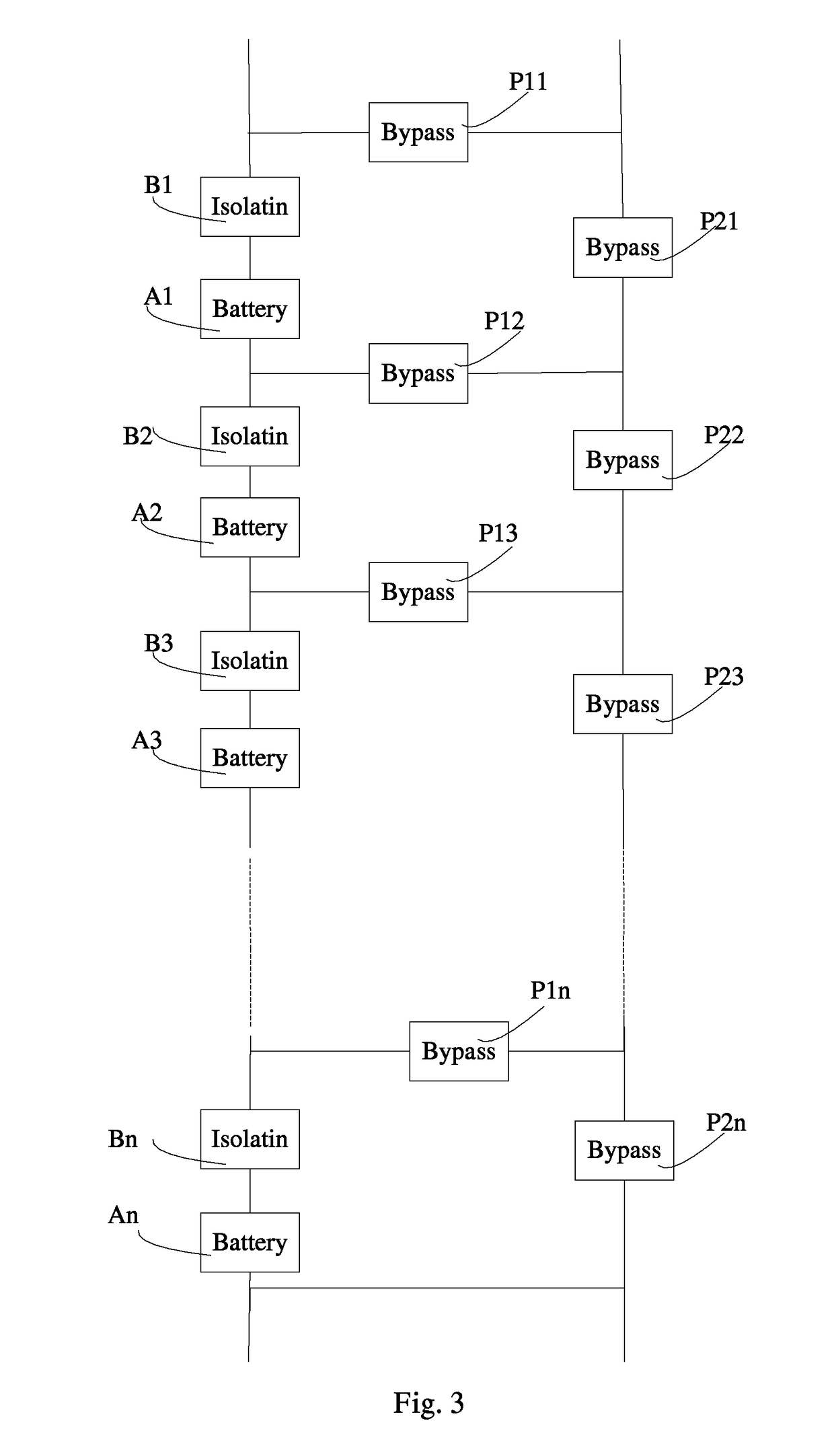
[0054]In the method described in FIGS. 4c to 4d, there is provided a battery management method allowing the isolation and bypass of a single cell for the purpose of quiescent recovery. As shown in FIG. 4d, the host controller deactivates the battery cell A2 of the battery management unit U2 by turning off the isolation element B2, turning on the bypass elements P12, P22 and P13. Meanwhile, the host controller keeps the battery cell A1, and A3 to An being activated by keeping isolation element B1, B3 to Bn on and bypass elements P11, P14 to P1n, P21, and P23 to P2n off.
[0055]After a period of quiescent recovery the battery cell A2 is reconnected by ensuring that isolation elements B2 is turned on and bypass elements P12, P22 and P13 are turned off, which is shown in FIG. 4c. This is then repeated alternately for every battery cell in the series string under the management of the host controller thus ensuring that every battery cell benefits from a period of quiescent recovery. This c...
third embodiment
[0056]In the battery management method described in FIGS. 4a to 4c, there is provided a battery management method allowing the isolation and bypass of multiple battery cells simultaneously by the host controller thus providing the ability to “soft start” the battery management system to reduce high inrush current spikes which may damage or reduce the battery performance in any way. As shown in FIGS. 4a and 4b, the battery cell A1 is activated by the host controller firstly, and the battery cell A2 is activated subsequently. This can be repeated incrementally for every battery cell in the battery management system over a short time period on an initial demand under the management of the host controller until the full battery pack voltage is available for the application, as shown in FIG. 4c, thus reducing high inrush current spikes which may damage or reduce the battery cells performance in any way.
fourth embodiment
[0057]In the battery management method described in FIGS. 4a to 4d, there is provided a battery management method allowing a variable voltage regulation and speed control for a motor based system such as an electric vehicle. A host controller decides the number of the battery cells that should be activated in response to an external demand, and then turning on or off related isolation elements and bypass elements. In this embodiment, the requirement for a separate speed controller may be mitigated which will represent a cost saving for the overall system.
PUM
| Property | Measurement | Unit |
|---|---|---|
| period of time | aaaaa | aaaaa |
| of time | aaaaa | aaaaa |
| time | aaaaa | aaaaa |
Abstract
Description
Claims
Application Information
 - R&D
- Intellectual Property
- Life Sciences
- Materials
- Tech Scout
- Unparalleled Data Quality
- Higher Quality Content
- 60% Fewer Hallucinations
Browse by: Latest US Patents, China's latest patents, Technical Efficacy Thesaurus, Application Domain, Technology Topic, Popular Technical Reports.
© 2025 PatSnap. All rights reserved.Legal|Privacy policy|Modern Slavery Act Transparency Statement|Sitemap|About US| Contact US: help@patsnap.com


