
Battery management system and method

Active Publication Date: 2013-09-12
CHEEVC
View PDF13 Cites 29 Cited by
  • Summary
  • Abstract
  • Description
  • Claims
  • Application Information

AI Technical Summary

Benefits of technology

The invention improves the performance and feature set of batteries by balancing usage and stress on individual battery management units. The host controller can start from a top, bottom, or intermediate battery management unit and cycle through each cell in a battery cell string to reduce stress and extend performance. The method also includes gradually activating all battery management units to reduce high inrush current spikes that can damage battery performance.

Problems solved by technology

The most stressful situation for a battery's working environment is to be under a constant and heavy load.
These units are relatively bulky and represent an increase in weight and cost which is particularly significant for a light electric vehicle or electric bike.
A Photovoltaic array operated under lower light conditions such as in Northern latitudes or on an overcast day for example may not achieve the output voltage required to charge a battery system.
But Shunsuke Koyama et al do not disclose or suggest a system or method that can be applied for managing a plurality of battery cells connected with each other in series, especially in light electric vehicles.

Method used


Image

  • Battery management system and method
  • Battery management system and method
  • Battery management system and method

Examples


second embodiment

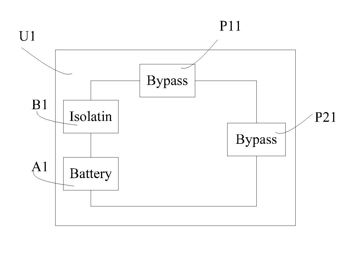
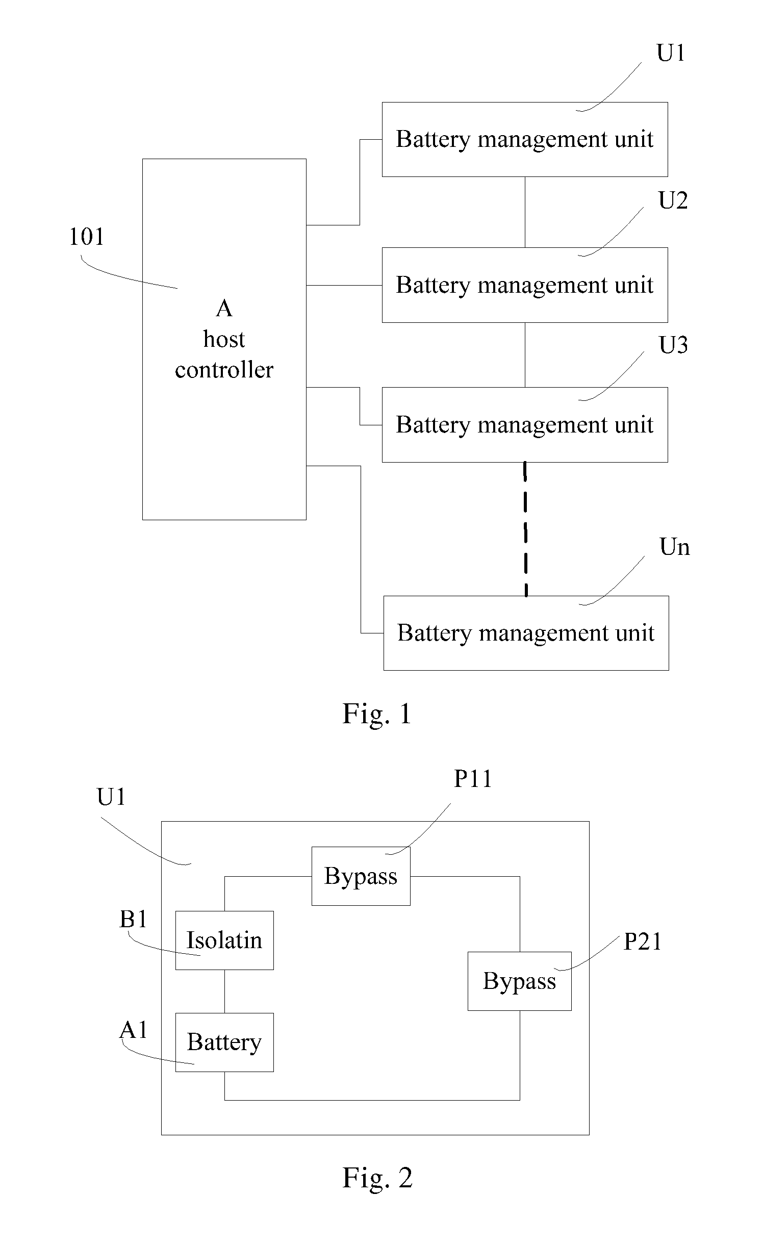
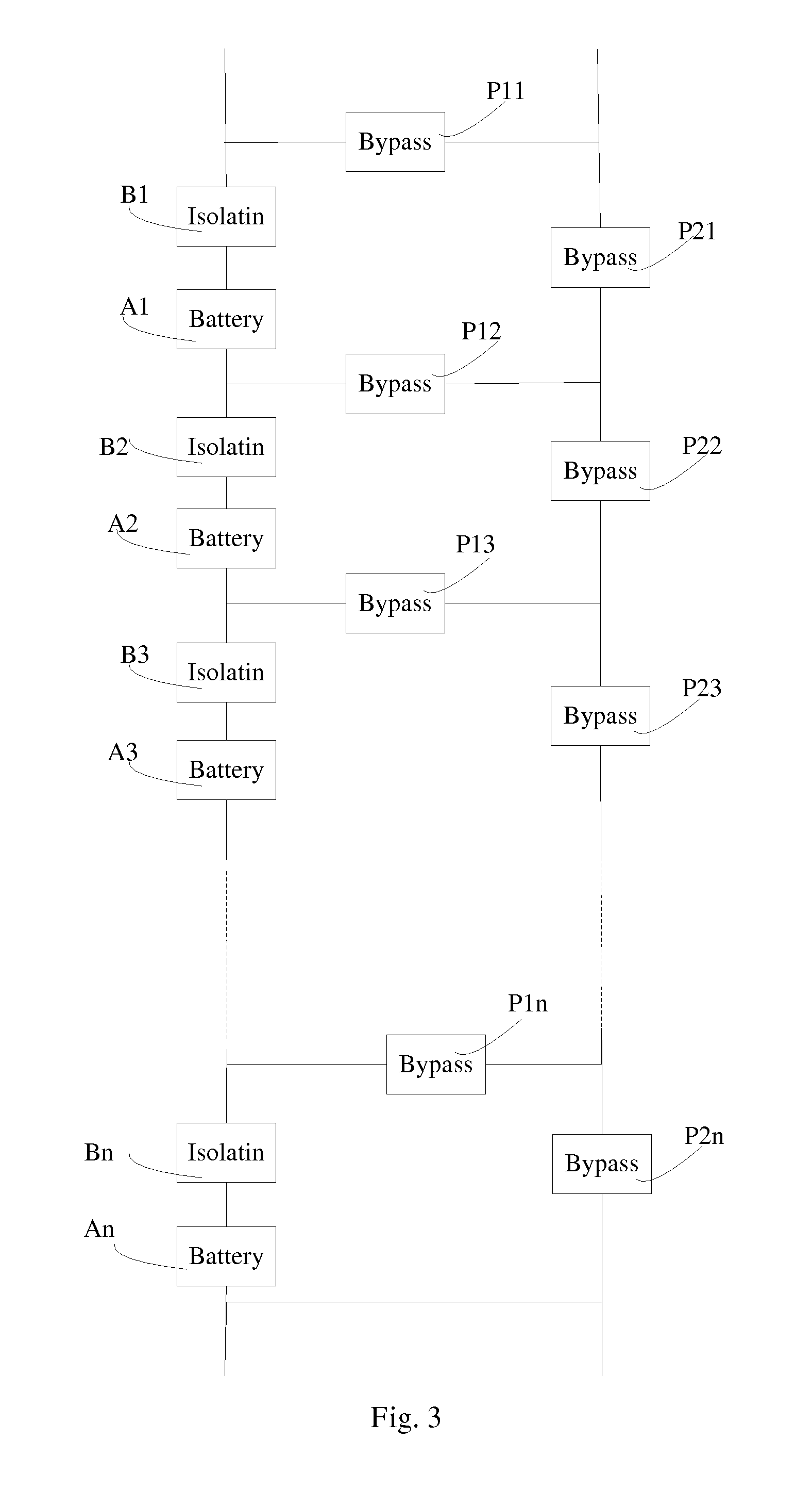
[0053]In the method described in FIGS. 4c to 4d, there is provided a battery management method allowing the isolation and bypass of a single cell for the purpose of quiescent recovery. As shown in FIG. 4d, the host controller deactivates the battery cell A2 of the battery management unit U2 by turning off the isolation element B2, turning on the bypass elements P12, P22 and P13. Meanwhile, the host controller keeps the battery cell A1, and A3 to An being activated by keeping isolation element B1, B3 to Bn on and bypass elements P11, P14 to P1n, P21, and P23 to P2n off.

[0054]After a period of quiescent recovery the battery cell A2 is reconnected by ensuring that isolation elements B2 is turned on and bypass elements P12, P22 and P13 are turned off, which is shown in FIG. 4c. This is then repeated alternately for every battery cell in the series string under the management of the host controller thus ensuring that every battery cell benefits from a period of quiescent recovery. This c...

third embodiment

[0055]In the battery management method described in FIGS. 4a to 4c, there is provided a battery management method allowing the isolation and bypass of multiple battery cells simultaneously by the host controller thus providing the ability to “soft start” the battery management system to reduce high inrush current spikes which may damage or reduce the battery performance in any way. As shown in FIGS. 4a and 4b, the battery cell A1 is activated by the host controller firstly, and the battery cell A2 is activated subsequently. This can be repeated incrementally for every battery cell in the battery management system over a short time period on an initial demand under the management of the host controller until the full battery pack voltage is available for the application, as shown in FIG. 4c, thus reducing high inrush current spikes which may damage or reduce the battery cells performance in any way.

fourth embodiment

[0056]In the battery management method described in FIGS. 4a to 4d, there is provided a battery management method allowing a variable voltage regulation and speed control for a motor based system such as an electric vehicle. A host controller decides the number of the battery cells that should be activated in response to an external demand, and then turning on or off related isolation elements and bypass elements. In this embodiment, the requirement for a separate speed controller may be mitigated which will represent a cost saving for the overall system.


PUM


Abstract

A battery management system can be provided which can include a plurality of battery management units connected in series and a host controller. Each battery management unit can include a battery cell, an isolation element, and at least one bypass element. The isolation element is connected with the battery cell in series, and the battery cell is isolated by turning off the isolation element. The bypass elements can be in parallel connection with the battery cell and isolation element, and the battery cell is bypassed by turning on the bypass element. A battery management method can include: activating the battery cell of the battery management unit by turning on the isolation element and turning off the bypass elements of the battery management unit; and deactivating the battery cell of the battery management unit by turning off the isolation element and turning on the bypass elements of the battery management unit.

Description

FIELD OF THE INVENTION[0001]The present invention relates to the field of battery management, and particularly to a battery management system and method for improving the reliability and extending the performance of Lithium battery packs appropriate to light electric vehicles.BACKGROUND OF THE INVENTION[0002]The most stressful situation for a battery's working environment is to be under a constant and heavy load. This is exactly the characteristic of an electric vehicle application. A battery with an intermittent load allows a level of electrochemical recovery during periods of very low or zero load. This is especially evident in Lead Acid cells but is a feature of all cell chemistries. Because of the time-constant associated with this behavior, a quiescent rest period is especially beneficial in extending the operating lifetime. A redundant cell isolation philosophy enables this recovery.[0003]In an electric vehicle application there is a requirement for an additional motor speed c...

Claims


Application Information

Patent Timeline
IPC IPC(8): H02J7/00
CPCH01M10/441H02J7/007Y02T10/7055H02J7/0016Y02T10/70Y02E60/10H01M10/42H01M10/44H02J7/00H01M10/4207H02J7/0014
Inventor NORTON, KENNETH HAMILTON
Owner CHEEVC
Learn More