Battery pack assembly

Inactive Publication Date: 2013-09-12
CHEEVC
View PDF3 Cites 19 Cited by
  • Summary
  • Abstract
  • Description
  • Claims
  • Application Information

AI Technical Summary

Benefits of technology

[0029]Consequently the phase change material used by the present invention equalizes the temperature potentials of every battery cell in the pack, thus improv

Problems solved by technology

One known issue with Dynamic or Active Battery Cell Balancing is that its effectiveness is compromised by variations in temperature across the pack.
If the individual state of charge (SOC) estimation is not made at the same thermal potential then the charge balancing system is not able to make accurate judgments on the need to transfer charge.
A weakness and source of premature failure in current multi-cell battery packs is the tab bonding used to interconnect the battery cells.
The tabs are spot-welded in a process which injects heat locally, an undesirable action which promotes premature failure.

Method used


Image

  • Battery pack assembly
  • Battery pack assembly
  • Battery pack assembly

Examples


first embodiment

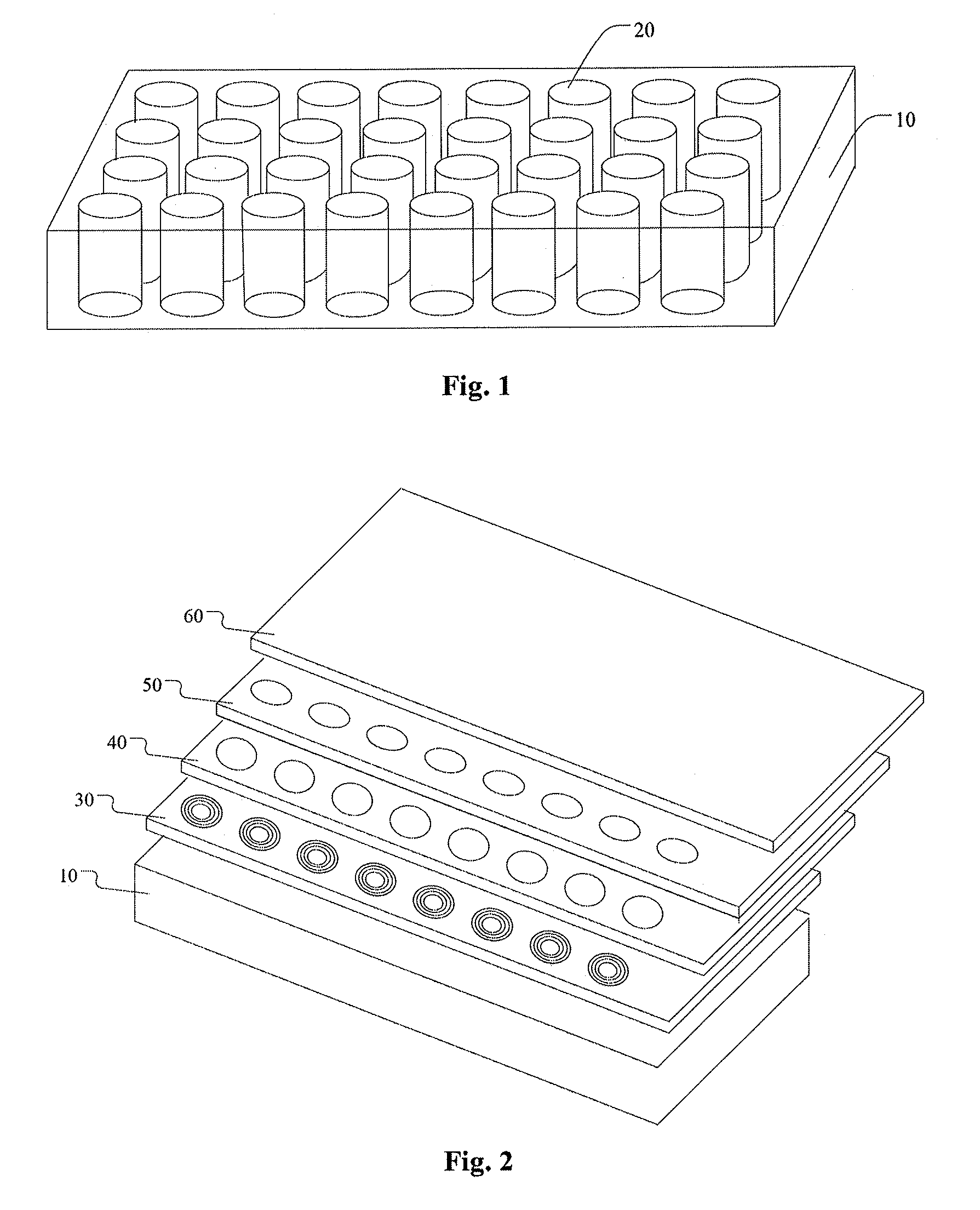
[0040]FIG. 2 illustrates a perspective exploded view of a battery pack assembly according to the present invention. The battery pack assembly comprises: the caddy 10, the battery cells 20 (not shown in FIG. 2), a soft and malleable pad 30, a plastic cell lattice 40, a Printed Circuit Board 50, a lid 60 and a plurality of ultrasonic wire or ribbon bonds 70. As shown in FIG. 2, the caddy 10 retains the battery cells 20; the soft and malleable pad 30 is set on the top of battery cells 20; the plastic cell lattice 40 is set on the top of the soft and malleable pad 30; the Printed Circuit Board 50 is set on the caddy 10 and on the top of the plastic cell lattice 40; the lid 60 is mounted on the caddy 10 and is adapted for sealing the caddy 10; the plurality of ultrasonic wire or ribbon bonds 70 (shown in FIGS. 6 and 7) directly connects positive contacts and negative contacts of the battery cells with the Printed Circuit Board 50.

[0041]FIG. 3 illustrates a schematic perspective view of a...

second embodiment

[0047]FIG. 8 illustrates a schematic cross section view of the battery pack assembly according to the present invention.

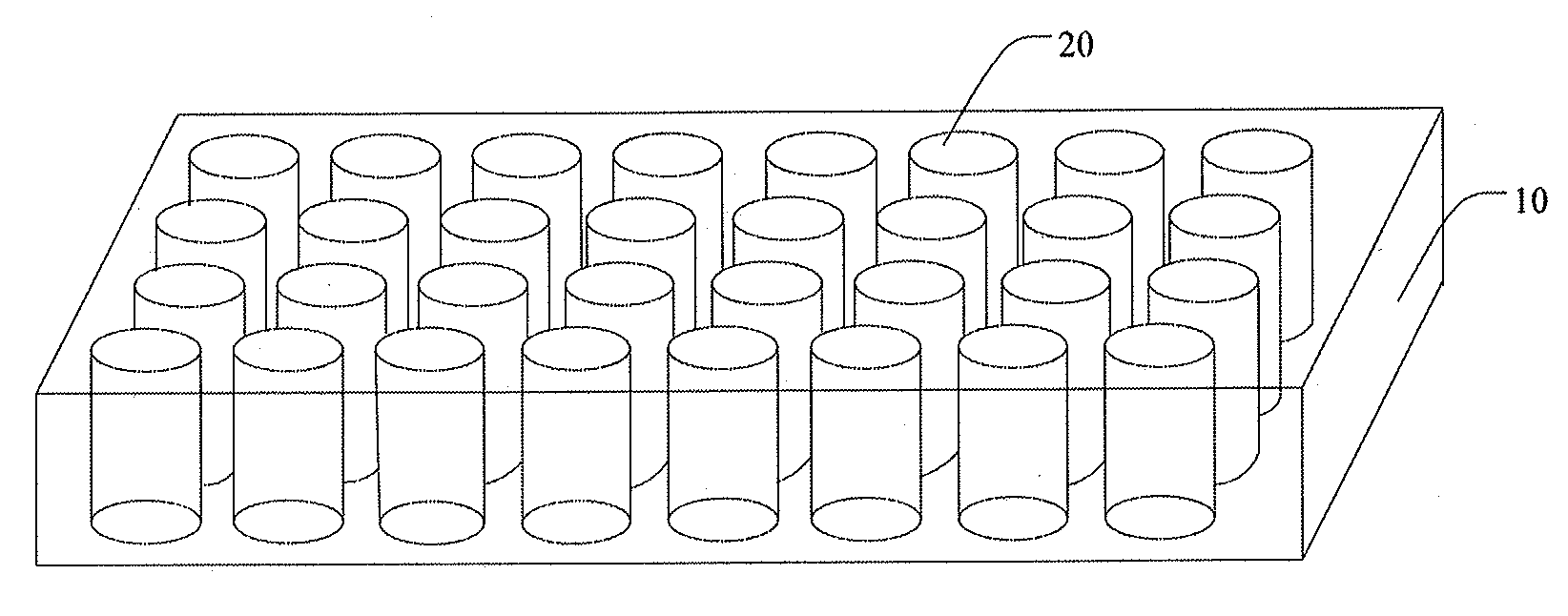
[0048]As shown in FIG. 1, the battery pack assembly comprises a plurality of battery cells 20 retained in a caddy 10 for both shipment and assembly. Referring to FIG. 8, the battery pack assembly further comprises a phase change material 90, a soft and malleable pad 30 and a lid 60 for sealing the caddy 10. There is only one battery cell 201 in FIG. 8, the cross section views and top views of other battery cells are the same with the battery cell 201, and are not shown in the figures.

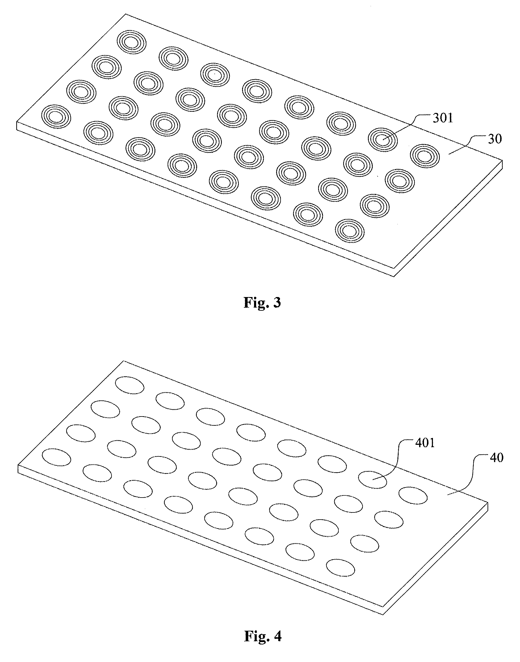
[0049]FIG. 3 illustrates a schematic perspective view of the soft and malleable pad 30 according to the present invention. Referring to FIG. 3, the soft and malleable pad 30 includes a first group of apertures 301, which are appropriately featured to expose the upper portion of each battery cell. The soft and malleable pad 30 is set on the top of battery cells for compensating for a ch...


PUM


Abstract

A battery pack assembly allowing automated single ended bonding directly between a battery cell and a Printed Circuit Board (PCB) is disclosed. The pack assembly comprises: a caddy, soft and malleable pad, plastic cell lattice, PCB, and plurality of ultrasonic wire or ribbon bonds. The pad includes a first group of apertures and is set on the top of battery cells. The cell lattice includes a second group of apertures and is set on the top of the pad. The PCB includes a third group of apertures and is set on the top of the cell lattice. The ultrasonic wire or ribbon bonds directly connect positive contacts and negative contacts of the battery cells with the PCB. A battery pack assembly allowing equalizing of the temperature potentials of every battery cell in the pack is also disclosed. The pack assembly comprises: a phase change material, soft and malleable pad, and caddy.

Description

FIELD OF THE INVENTION[0001]The present invention relates to the field of improving the reliability and extending the performance of Lithium battery packs in general, and particularly to battery pack assembly techniques appropriate to light electric vehicles.BACKGROUND OF THE INVENTION[0002]One known issue with Dynamic or Active Battery Cell Balancing is that its effectiveness is compromised by variations in temperature across the pack. Battery cell temperatures vary due to differences in individual chemical compositions and internal to resistances. If the individual state of charge (SOC) estimation is not made at the same thermal potential then the charge balancing system is not able to make accurate judgments on the need to transfer charge.[0003]If the pack is assembled with a technical grade wax jacket surrounding each battery cell then the temperature can be equalized to be homogenous across the pack. The wax acts as a phase change material, rapidly melting at a relatively low t...

Claims


Application Information

Patent Timeline
IPC IPC(8): H01M10/50H01M50/213H01M50/271H01M50/516H01M50/519
CPCH01M2/1077H01M2/206H01M10/425H01M10/5004H01M10/5055H01M10/5089H01M10/5008H01M10/6555H01M10/617H01M10/659H01M10/613Y02E60/10H01M50/519H01M50/213H01M50/516H01M50/271H01M10/60
Inventor NORTON, KENNETH HAMILTON
Owner CHEEVC
Why Eureka
Try Eureka