Contactless power transmission device and power transfer system

a transmission device and power transfer technology, applied in the direction of electric variable regulation, process and machine control, instruments, etc., can solve the problems of transmission power exceeding the limit value unexpectedly

Active Publication Date: 2018-10-09
TOYOTA JIDOSHA KK
View PDF80 Cites 0 Cited by
  • Summary
  • Abstract
  • Description
  • Claims
  • Application Information

AI Technical Summary

Benefits of technology

[0009]It is therefore an object of the present invention to provide a contactless power transmission device that transmits electric power to a power reception device in a contactless manner which prevents transmission power from exceeding a limit value when the drive frequency of an inverter is adjusted.
[0010]It is another object of the present invention to provide a power transfer system that transmits electric power from a power transmission device to a power reception device in a contactless manner which prevents transmission power from exceeding a limit value when the drive frequency of an inverter of the power transmission device is adjusted.
[0013]In the above aspects of the present invention, the target power is decreased when the transmission power exceeds the limit value. With the decrease of the target power, the transmission power is decreased. Therefore, the transmission power can be prevented from exceeding the limit value.
[0015]With such a configuration, the transmission power exceeding the limit value can be reduced quickly with a simple configuration.
[0017]With such a configuration, when the transmission power exceeds the limit value, the transmission power is limited to the limit value. It is therefore possible to prevent the transmission power from exceeding the limit value with reliability and to minimize the amount of decrease of the target power.

Problems solved by technology

When the transmission power changes with the adjustment of the drive frequency, the transmission power may exceed a limit value unexpectedly.
When the drive frequency of the inverter is adjusted, an overshoot of the transmission power may occur, so that the transmission power may exceed the limit value unexpectedly.

Method used


Image

  • Contactless power transmission device and power transfer system
  • Contactless power transmission device and power transfer system
  • Contactless power transmission device and power transfer system

Examples


Embodiment Construction

[0030]Hereinafter, an embodiment of the present invention will be described in detail with reference to the drawings. In the drawings, the same or corresponding portions have the same reference characters allotted, and description thereof will not be repeated.

[0031](Configuration of Power Transfer System)

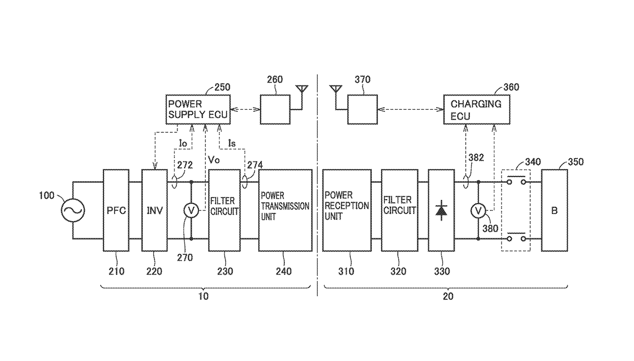
[0032]FIG. 1 shows an overall configuration of a power transfer system to which a contactless power transmission device according to an embodiment of the present invention is applied. Referring to FIG. 1, this power transfer system includes a power transmission device 10 and a power reception device 20. Power reception device 20 may be mounted on a vehicle or the like that can travel using electric power supplied from power transmission device 10 and stored therein, for example.

[0033]Power transmission device 10 includes a power factor correction (PFC) circuit 210, an inverter 220, a filter circuit 230, and a power transmission unit 240. Power transmission device 10 further includes...


PUM


Abstract

A control unit executes a first control and a second control. The first control is to control transmission power to target power by adjusting a duty of an output voltage of an inverter. The second control is to control a turn-on current by adjusting the drive frequency, the turn-on current indicating an output current of the inverter at a rising of the output voltage. When the transmission power exceeds a limit value larger than the target power during adjustment of the drive frequency by the second control, the control unit decreases the target power in the first control.

Description

[0001]This nonprovisional application is based on Japanese Patent Application No. 2015-143938 filed on Jul. 21, 2015 with the Japan Patent Office, the entire contents of which are hereby incorporated by reference.BACKGROUND OF THE INVENTION[0002]Field of the Invention[0003]The present invention relates to a contactless power transmission device and a power transfer system, and particularly to a power control technique in a contactless power transmission device that transmits electric power to a power reception device in a contactless manner.[0004]Description of the Background Art[0005]Japanese Patent Laying-Open No. 2014-207795 discloses a contactless power feeding system that supplies electric power from a power feeding device (power transmission device) to a vehicle (power reception device) in a contactless manner. In this contactless power feeding system, the power feeding device includes a power transmission coil, an inverter and a control unit. The power transmission coil trans...

Claims


Application Information

Patent Timeline
Patent Type & Authority Patents(United States)
IPC IPC(8): H02J50/12H02J7/04H02M3/337H02J7/02H02M1/00
CPCH02J50/12H02J7/025H02M3/3376Y02B70/1491H02M2001/0051H02M2001/0058H02M2001/0025H02J7/00034H02J50/80Y02B70/10H02M1/0025H02M1/0051H02M1/0058
Inventor MISAWA, TAKAHIRO
Owner TOYOTA JIDOSHA KK
Why Eureka
Try Eureka