
Method for controlling motor-driven compressor configured to be installed in vehicle

a technology of motor-driven compressors and configurations, which is applied in the direction of positive displacement liquid engines, piston pumps, lighting and heating apparatuses, etc., can solve the problems of increasing or decreasing the number of times, aggravating noise and vibration (nv), and damaging the switching elements of the inverter

Active Publication Date: 2017-10-05
TOYOTA IND CORP
View PDF0 Cites 2 Cited by
  • Summary
  • Abstract
  • Description
  • Claims
  • Application Information

AI Technical Summary

Benefits of technology

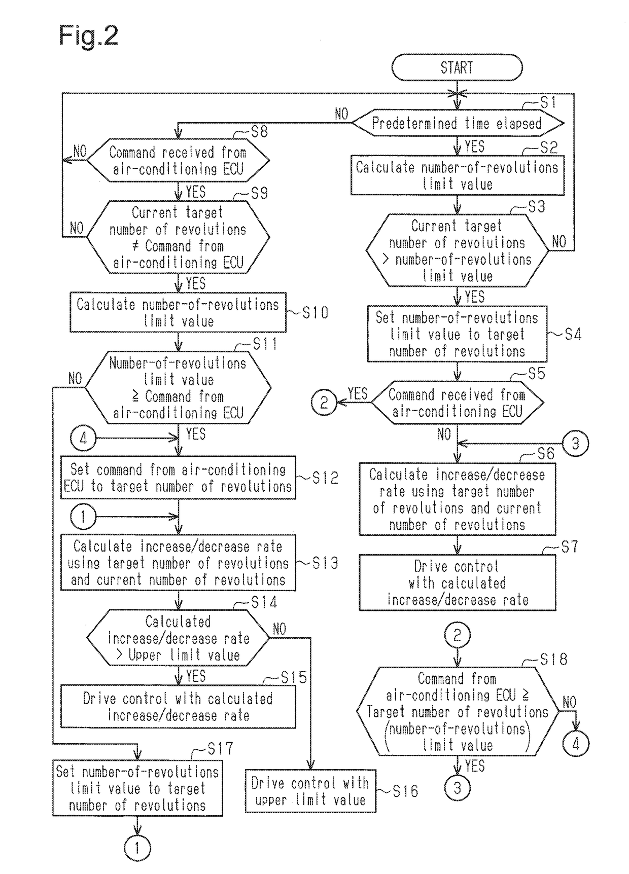
The present invention provides a method for controlling a motor-driven compressor in a vehicle to prevent damage to the compressor's switching elements and to restrain a sudden change in the motor's revolutions per minute (RPM) when a rapid voltage change occurs in the vehicle battery. The control section of the compressor sets a target RPM and controls the electric motor to achieve that target speed. The control section changes the motor's RPM at a slower rate than the maximum allowed increase or decrease rate to prevent damage to the switches. Additionally, the control section can decrease the motor's RPM beyond the maximum allowed decrease rate if the battery voltage exceeds a predetermined limit. This method and apparatus can protect the motor-driven compressor and ensure stable operation of the vehicle's battery.

Problems solved by technology

Therefore, if the number of revolutions is changed frequently in response to commands by the control device, rapid increase or decrease of the number of revolutions repeatedly happens, thus aggravating noise and vibration (NV).
At this time, if the counter electromotive voltage of the motor is high, an excessive electric current flows through the inverter, thus damaging the switching elements of the inverter.
Thus, the power source voltage of the motor-driven compressor can rapidly decrease in some cases.
An excessive electric current may thus flow through the battery, damaging the inverter.
However, this increases costs and enlarges the inverter.
However, the publication does not include description regarding damage to the switching elements of the inverter caused by stopping the motor-driven compressor operating at a high number of revolutions when the battery voltage is low.

Method used


Image

  • Method for controlling motor-driven compressor configured to be installed in vehicle
  • Method for controlling motor-driven compressor configured to be installed in vehicle
  • Method for controlling motor-driven compressor configured to be installed in vehicle

Examples


Embodiment Construction

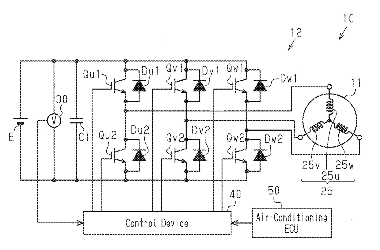
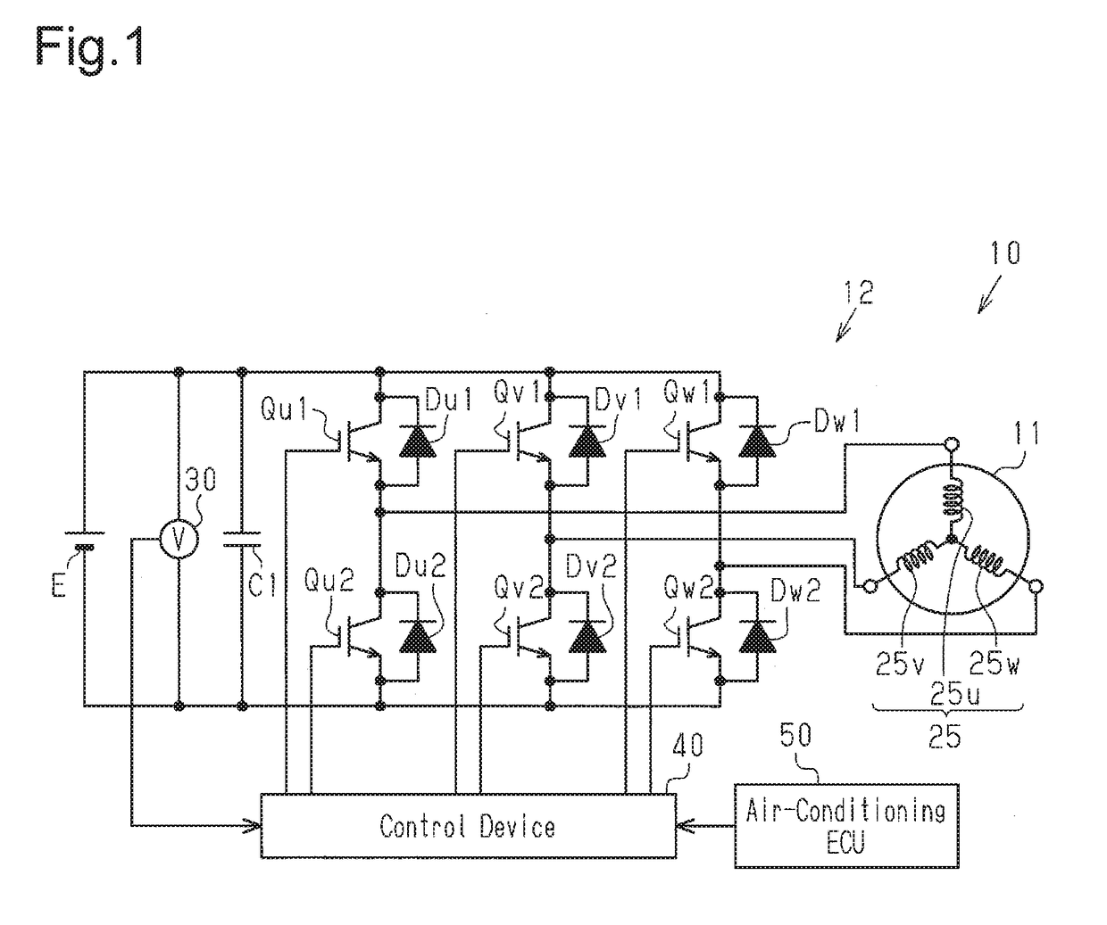
[0018]A method for controlling a motor-driven compressor configured to be installed in a vehicle according to one embodiment of the present invention will now be described with reference to FIGS. 1 to 3.

[0019]A motor-driven compressor is used in an air conditioner configured to be installed in a vehicle. The motor-driven compressor includes a compressing portion, which compresses and discharges refrigerant, an electric motor serving as a drive source of the compressing portion, and an inverter that drives the electric motor.

[0020]As shown in FIG. 1, a motor-driven compressor 10 includes an electric motor11 and an inverter 12 serving as a drive circuit that drives the electric motor 11. A coil 25 of the electric motor 11 has a three-phase structure having a u-phase coil 25u, a v-phase coil 25v, and a w-phase coil 25w. The electric motor 11 is a three-phase motor. The u-phase coil 25u, the v-phase coil 25v, and the w-phase coil 25w are connected in a Y-connection.

[0021]The inverter 12...


PUM


Abstract

The control section controls the electric motor to be driven such that the number of revolutions becomes equal to the target number of revolutions. If the control section sets the target number of revolutions to a number of revolutions of the electric motor requested by another control section, the control section changes the number of revolutions of the electric motor at an increase rate lower than or equal to the upper limit value of the increase rate or at a decrease rate lower than or equal to the upper limit value of the decrease rate. If the control section sets the target number of revolutions to a number-of-revolutions limit value, which is determined based on the voltage of a vehicle battery, the control section is able to decrease the number of revolutions of the electric motor at a decrease rate exceeding the upper limit value.

Description

BACKGROUND OF THE INVENTION[0001]The present invention relates to a method for controlling a motor-driven compressor configured to be installed in a vehicle.[0002]Conventionally, there is a motor-driven compressor that is configured to be installed in a vehicle and is driven by an inverter. The inverter receives electric power from a battery of a vehicle and converts DC power into AC power. The motor-driven compressor is driven at a number of revolutions commanded by a control device installed in the vehicle. The number of revolutions commanded by the control device is represented by discrete values. Therefore, if the number of revolutions is changed frequently in response to commands by the control device, rapid increase or decrease of the number of revolutions repeatedly happens, thus aggravating noise and vibration (NV). To solve this problem, as shown in FIG. 4, the motor-driven compressor is driven at a number of revolutions having a change per unit time that is lower than that...

Claims


Application Information

Patent Timeline
Patent Type & Authority Applications(United States)
IPC IPC(8): F04D27/00F04C28/08B60H1/32F04B27/08F04B35/04F04B49/20F04D25/06F04C29/00
CPCF04D27/004F04D25/0673F04C28/08F04C29/0085F04B27/08F04B35/04B60H2001/3272B60H1/3222B60H1/3205F04C2240/40F04C2270/051B60H2001/3292F04B49/20F04B49/06F04B2203/0209H02P7/00F04B49/02F04C23/008F04C2240/403F04C2270/0525F04C2270/605Y02B30/70B60H1/3225F25B49/022F25B49/025F25B2600/024F25B2600/0253
Inventor KAWASHIMA, TAKASHINAGATA, YOSHIKINAJIMA, KAZUKI
Owner TOYOTA IND CORP
Learn More