Power conversion apparatus

a technology of power conversion apparatus and power conversion device, which is applied in the direction of pulse manipulation, pulse technique, and semiconductor/solid-state device details, etc., can solve the problems of increasing reducing the amount of heat generation (loss), and difficulty in reducing the manufacturing cost of power conversion apparatus, so as to reduce the manufacturing cost of the power conversion apparatus. the effect of high resistance to the surge of the turn-off speed

Active Publication Date: 2019-05-28
DENSO CORP
View PDF19 Cites 0 Cited by
  • Summary
  • Abstract
  • Description
  • Claims
  • Application Information

AI Technical Summary

Benefits of technology

[0012]An embodiment provides a power conversion apparatus that can prevent an element temperature from exceeding an upper limit value, that is highly resistant to turn-off surge, and that can reduce the manufacturing cost thereof.
[0020]Hence, an element temperature can be prevented from exceeding an upper limit value, and the manufacturing cost of the power conversion apparatus can be reduced. That is, when the coolant temperature is high, the controller increases the turn-off speed. Hence, when the coolant temperature is high, and it is difficult to cool the semiconductor element, the amount of heat generation of the semiconductor element can be reduced. Accordingly, the element temperature is easily prevented from exceeding the upper limit value. Hence, even if the area of the semiconductor element is decreased to increase the amount of heat generation per unit area, it becomes difficult for the element temperature to exceed the upper limit value. Accordingly, the semiconductor element can be reduced in size, whereby the manufacturing cost thereof can be reduced.
[0021]In addition, when the coolant temperature is high, withstand voltage of the semiconductor element becomes high. When the coolant temperature is low, the withstand voltage becomes low. Hence, even if a high turn-off surge is generated by increasing the turn-off speed when the coolant temperature is high, the semiconductor element can be sufficiently protected from the turn-off surge because the withstand voltage of the semiconductor element is high. In addition, since the controller decreases the turn-off speed when the coolant temperature is low, the turn-off surge can be reduced. Hence, when the coolant temperature is low, and the withstand voltage is low, the turn-off surge can be reduced, whereby the semiconductor element can be protected from the turn-off surge.
[0022]As described above, according to the embodiment, a power conversion apparatus can be provided that can prevent an element temperature from exceeding an upper limit value, that is highly resistant to turn-off surge, and that can reduce the manufacturing cost thereof.

Problems solved by technology

That is, increasing the turn-off speed decreases the amount of heat generation (loss), and decreasing the turn-off speed increases the amount of heat generation.
However, the power conversion apparatus is difficult to reduce the manufacturing cost thereof while preventing the element temperature from exceeding the upper limit value.
Accordingly, although the coolant temperature is high, and it is difficult to cool the semiconductor element, the amount of heat generation becomes large.
Accordingly, the manufacturing cost of the semiconductor element easily increases.
Hence, even if the area of the semiconductor element is decreased to increase the amount of heat generation per unit area, it becomes difficult for the element temperature to exceed the upper limit value.

Method used


Image

  • Power conversion apparatus
  • Power conversion apparatus
  • Power conversion apparatus

Examples


first embodiment

[0049

[0050]An embodiment of the power conversion apparatus will be described with reference to FIG. 1 to FIG. 16. As shown in FIG. 10 to FIG. 12, a power conversion apparatus 1 of the present embodiment includes semiconductor modules 3 including semiconductor elements 2, a controller 4, a cooler 5, and temperature sensors 6.

[0051]The controller 4 is connected to the semiconductor modules 3 and controls switching operations of the semiconductor elements 2. In the cooler 5, flow paths 51 are formed through which a coolant 50 flows. The cooler 5 cools the semiconductor elements 2. The temperature sensors 6 are disposed in the flow paths 51 of the cooler 5. The temperature sensors 6 measure a coolant temperature Tr, which is a temperature of the coolant 50. The temperature sensors 6 are connected to the controller 4.

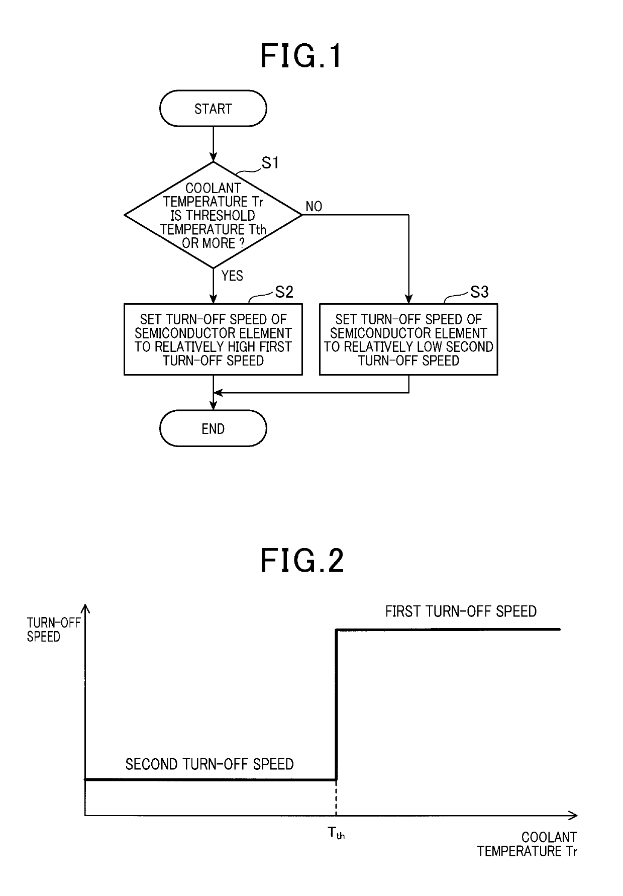
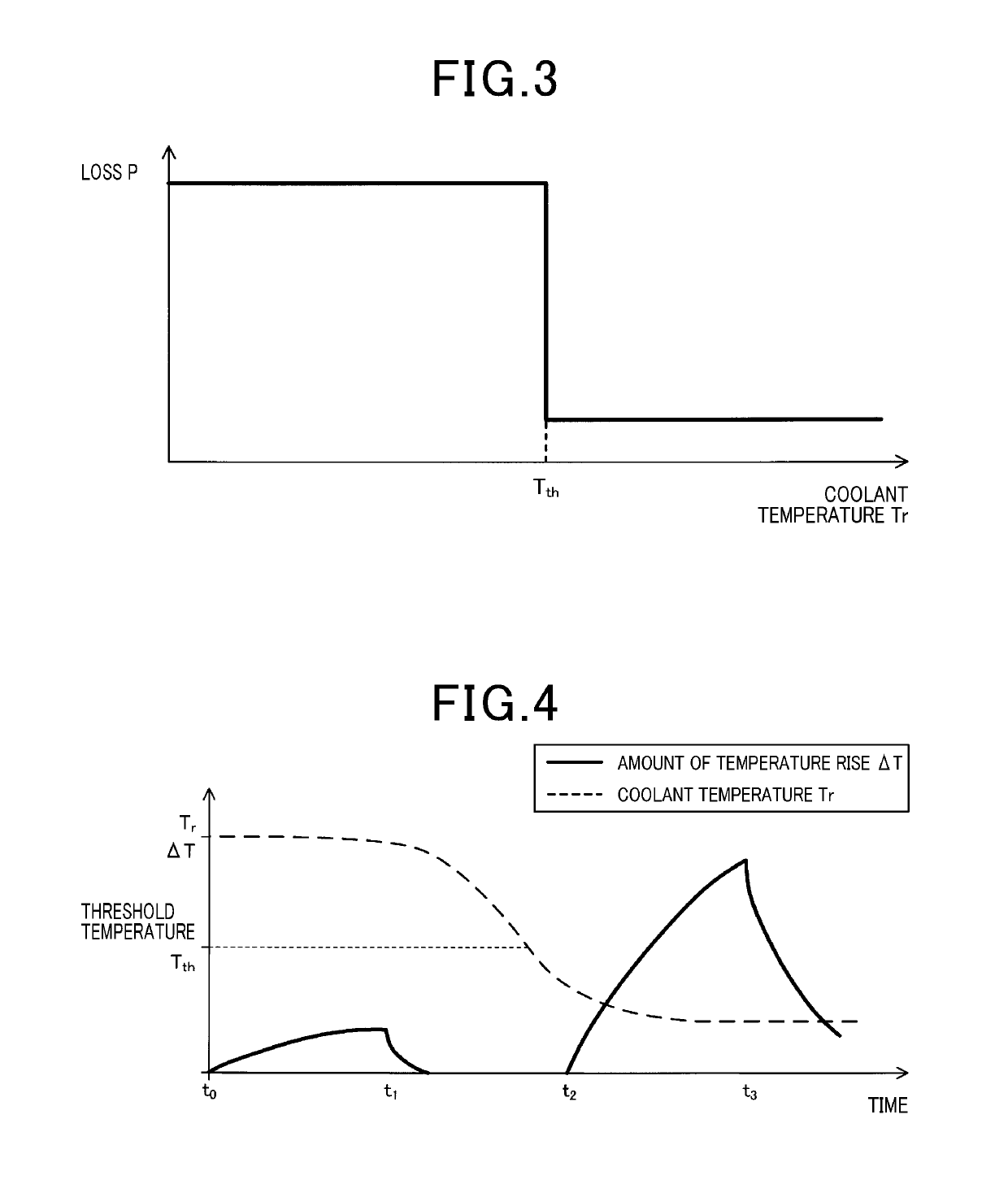
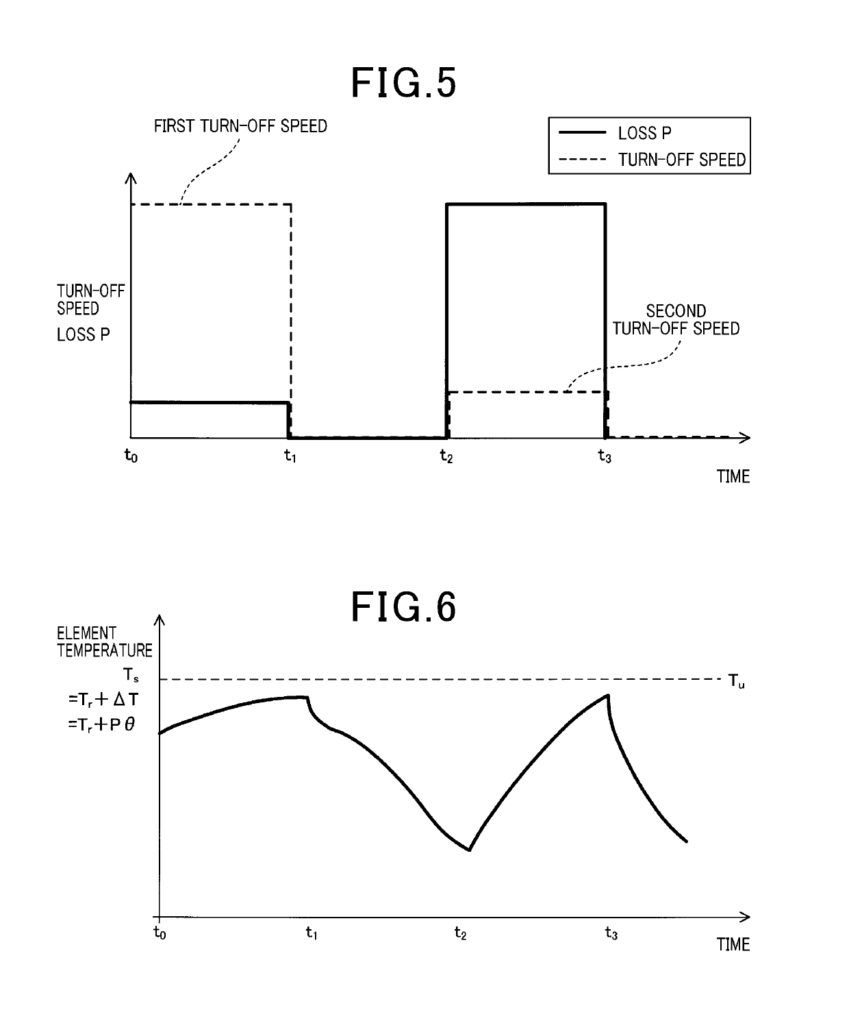
[0052]The controller 4 controls turn-off speed (off speed) of the semiconductor elements 2 based on the measurement value of the coolant temperature Tr. As shown in FIG. 2, ...

second embodiment

[0087

[0088]The present embodiment is an example in which the circuit configuration of the controller 4 is modified. As shown in FIG. 17, the controller 4 of the present embodiment includes a constant current circuit 47 connected between the control electrode 21 of the semiconductor element 2 and the ground. The constant current circuit 47 controls the value of the current Ig flowing from the control electrode 21 to the ground so as to be constant and can change the current value to a predetermined value. The controller 4 changes the value of the current Ig by using the constant current circuit 47 to control the turn-off speed of the semiconductor element 2.

[0089]The constant current circuit 47 includes a resistor Ra, a transistor 46, and a current controller 45. The resistor Ra and the transistor 46 are connected in series. In addition, the current controller 45 is connected to a base 461 of the transistor 46. The constant current circuit 47 feeds back the voltage drop, which is gen...

third embodiment

[0094

[0095]The present embodiment is an example in which the number of changing the turn-off speed is modified. As shown in FIG. 18, in the present embodiment, as the coolant temperature Tr rises, the turn-off speed is increased multiple times step by step. Hence, as shown in FIG. 19, as the coolant temperature Tr rises, the loss of the semiconductor element 2 decreases multiple times step by step.

[0096]In the present embodiment, since the turn-off speed is changed multiple times as the coolant temperature Tr rises, the turn-off speed can be a value more suitable for the coolant temperature Tr. Hence, the element temperature Ts can be prevented from exceeding the upper limit value Tu more effectively.

[0097]In addition, the third embodiment includes configurations and operational advantages similar to those of the first embodiment.


PUM


Abstract

A semiconductor module including a semiconductor element, a controller, a cooler, and a temperature sensor are included. The controller is connected to the semiconductor module and controls switching operation of the semiconductor element. The temperature sensor measures a coolant temperature, which is a temperature of the coolant. The controller controls turn-off speed of the semiconductor element based on the coolant temperature. The controller increases the turn-off speed as the coolant temperature rises.

Description

CROSS-REFERENCE TO RELATED APPLICATION[0001]This application is based on and claims the benefit of priority from earlier Japanese Patent Application No. 2016-030162 filed Feb. 19, 2016, the description of which is incorporated herein by reference.BACKGROUND[0002]Technical Field[0003]The present invention relates to a power conversion apparatus that includes a semiconductor module including semiconductor elements, a cooler cooling the semiconductor module, and a controller controlling switching operations of the semiconductor elements.[0004]Related Art[0005]As a power conversion apparatus converting between DC power and AC power, an apparatus is known that includes a semiconductor module, which includes semiconductor elements such as IGBTs, and a controller connected to the semiconductor module (refer to JP-A-2008-178200). The power conversion apparatus uses the controller to make the semiconductor elements perform switching operations, thereby converting DC power to AC power.[0006]S...

Claims


Application Information

Patent Timeline
Patent Type & Authority Patents(United States)
IPC IPC(8): H03K17/14H03K17/041H03K17/0412H05K7/20H01L29/00H03K17/16H02P27/08H03K17/04H03K3/011H02M1/08H02P29/68H03K17/08H03K5/00H02M7/00H02M1/00H02P27/06B60L50/16
CPCH03K17/14B60L50/16H02M1/08H02P27/085H02P29/68H03K3/011H03K17/04H03K17/041H03K17/0412H03K17/163H05K7/2089H01L29/00H02M7/003H02M2001/0003H02P27/06H03K2005/00032H03K2017/0806H01L23/473H01L23/34H01L23/4012H02M1/0003
Inventor YAMAHIRA, YUU
Owner DENSO CORP
Why Eureka
Try Eureka