
Method of manufacturing a rotor body of a Magnus-type rotor

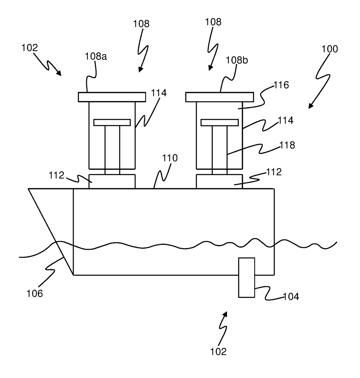
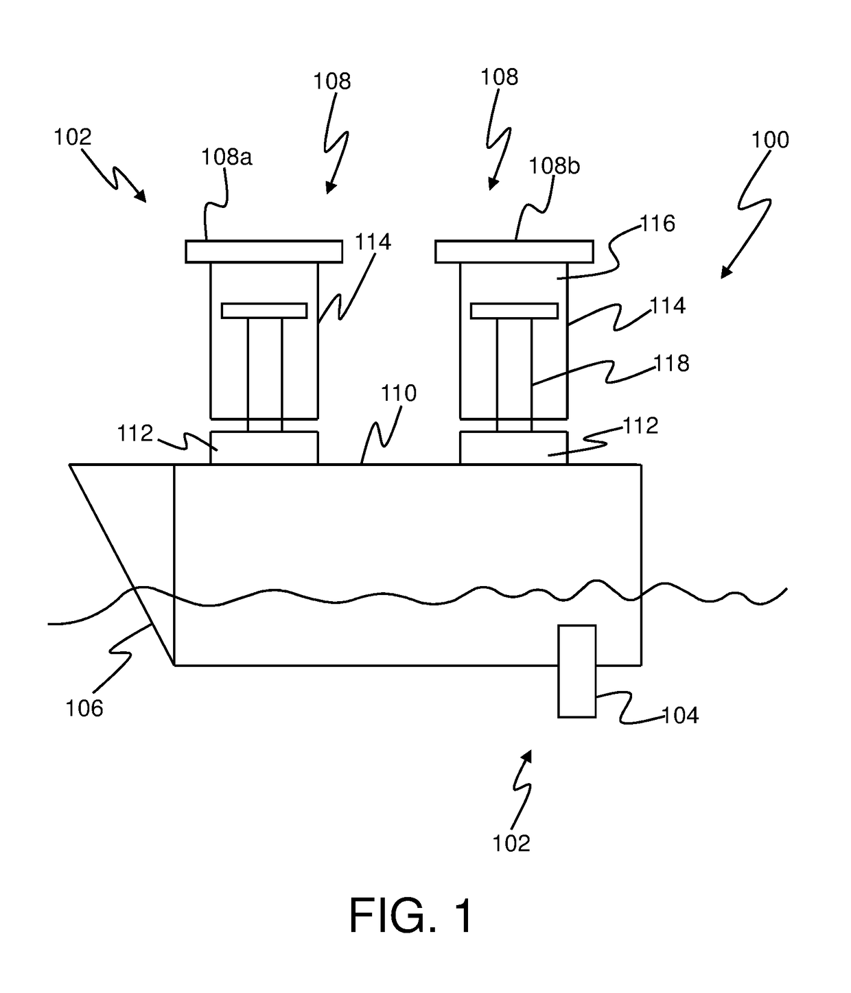
a technology of magnus-type rotors and manufacturing methods, which is applied in the field of magnus-type rotors, can solve the problems of large molds and associated system hardware or equipment, the method of manufacturing is potentially not applicable in the case of the magnus-type rotor, and the maintenance of magnus-type rotors is often difficult to achiev

Active Publication Date: 2018-10-16
NORSEPOWER OY
View PDF25 Cites 0 Cited by
  • Summary
  • Abstract
  • Description
  • Claims
  • Application Information

AI Technical Summary

Benefits of technology

[0017]Embodiments of the present disclosure are capable of substantially eliminating the aforementioned problems in the prior art. Further, embodiments of the present disclosure mitigate detrimental effects experienced by rotor bodies manufactured from previously known methods such as, but not limited to, high costs, high weight, uneven mass distribution, low and / or non-uniform stiffness, and deformation during operation of the rotor body. Furthermore, embodiments of the present disclosure impart flexibility to a manufacturer in terms of process control, assembly, and logistics.

Problems solved by technology

As such, manufacturers of Magnus-type rotors are often faced with challenges in maintaining various desirable structural properties and / or parameters in the Magnus-type rotors.
However, such methods of manufacturing are potentially not applicable in a case of the rotor body, because Magnus-type rotors are typically required to operate in conditions that are different to those of the cylindrical objects described in the '304 publication.
However, with the use of such techniques, large molds and associated system hardware or equipment are potentially required.
Moreover, time and labour required to manufacture the rotor body is often high.
Furthermore, costs associated with manufacturing, assembling, and logistics handling of the rotor body are also potentially high.
The aforesaid previously known techniques do not allow the manufacturing process to be controlled for obtaining or achieving desirable structural properties.
For example, rotor bodies produced from such previously known techniques potentially have a non-uniform mass distribution and / or a non-consistent stiffness in various cross-sectional and / or symmetrical planes of the rotor body.
Consequently, the rotor bodies produced from such previously known techniques are potentially subject to detrimental effects such as, but not limited to, uneven rotation, wobbling, and / or deformation in shape of the rotor body during operation.

Method used


Image

  • Method of manufacturing a rotor body of a Magnus-type rotor
  • Method of manufacturing a rotor body of a Magnus-type rotor
  • Method of manufacturing a rotor body of a Magnus-type rotor

Examples


first embodiment

[0071]As shown in FIG. 6, the rotor body 114 is shown including four loops 404a, 404b, 404c, and 404d. Although it has been disclosed herein that the loops 404a and 404b from the rotor body 114 of the first embodiment are optionally of similar or dissimilar heights h1, h2 (as defined on the basis of the heights h of the respective panels 402 therein), it is optionally possible to have different heights h for each panel 402 in the given loops 404a, 404b, 404c, and 404d as shown in the rotor body 114 of the first modified embodiment of FIG. 6.

first modified embodiment

[0072]Referring again to FIG. 6, the different heights can be, for example, h3, h4, h5, h6. The different heights of the individual panels give a staggered, tiered or toothed appearance to proximal ends 508a of the associated loops 404c and 404b. Upon stacking of the staggered, tiered or tooth shaped loops 404c and 404d in the rotor body 114, the rotor body 114 is rendered with an inter-fitting pattern. However, distal ends or edges 508b of panels 402 from loops 404c and 404d of the rotor body 114 can be formed in a straight-cut profile to allow fitment with other higher assemblies, for example, the loop 404b, that are located subsequent or adjacent to the rotor body 114. Optionally, such a straight-cut profile at distal ends 508b of the panels 402 from loops 404c and 404d of the rotor body 114 is optionally provided to adhere to pre-defined design parameters and / or to achieve pre-defined operational characteristics from the rotor body 114. Therefore, it is hereby envisaged that mod...


PUM

PropertyMeasurementUnit
heightaaaaaaaaaa
diameteraaaaaaaaaa
diameteraaaaaaaaaa

Abstract

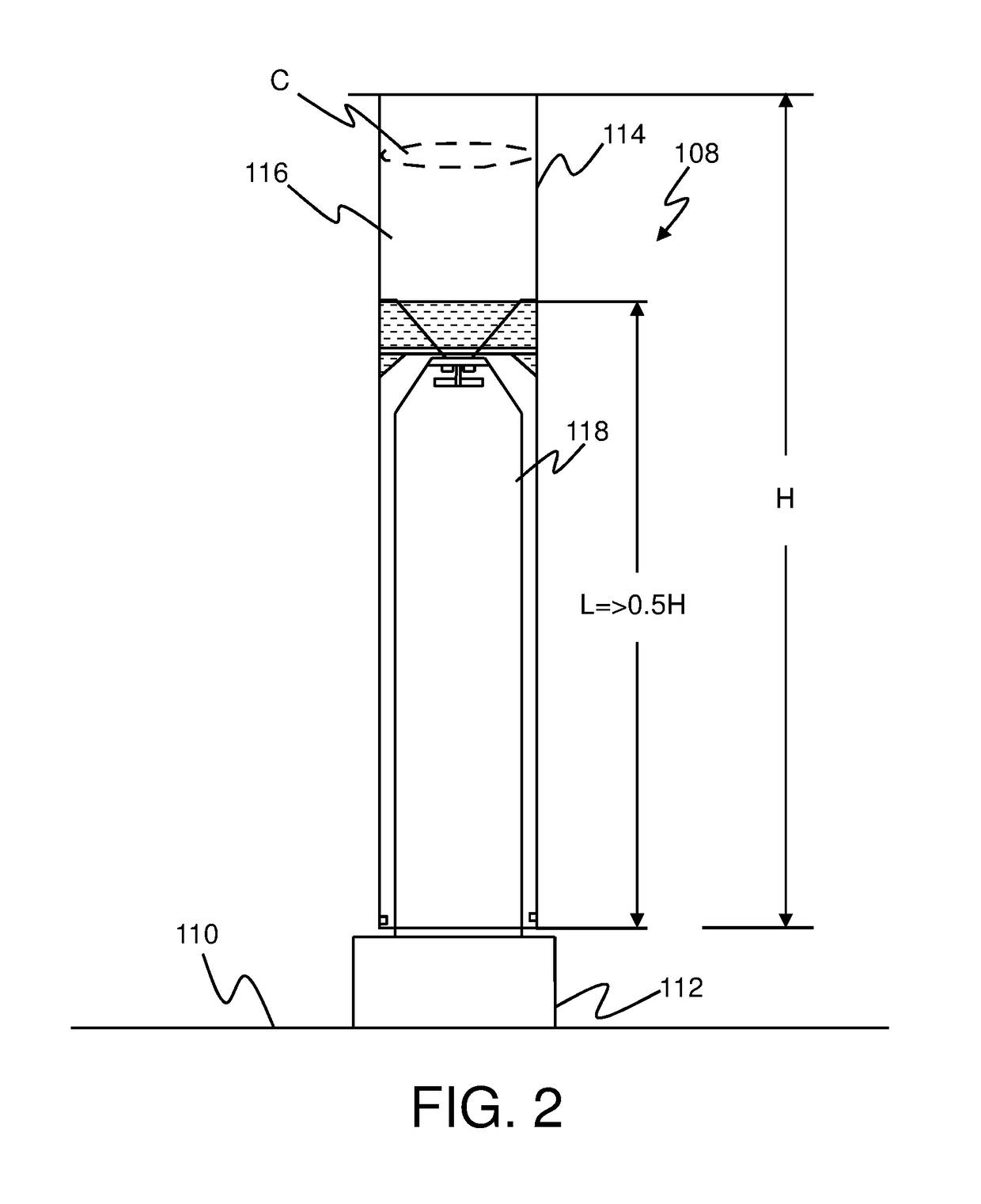
A method is provided for manufacturing a rotor body of a Magnus-type rotor. The method includes providing a plurality of arcuate panels, wherein each of the panels has an arc-length less than a predetermined circumference of the rotor body. The method further includes positioning at least three such arcuate panels in mutual edge-wise abutment to form circumferentially a hollow cylindrical loop, wherein longitudinal edges of adjacent panels are mutually attached to each other. The method further optionally includes co-axially stacking one above another at least two loops of substantially similar diameter. The method further includes connecting edges of adjacent loops to define the rotor body of a predetermined height.

Description

TECHNICAL FIELD[0001]The present disclosure generally relates to Magnus-type rotors for propelling aquatic vessels, and more specifically to methods of manufacturing a rotor body of the Magnus-type rotors.BACKGROUND[0002]Conventionally, a propulsion system for an aquatic vessel includes one or more propellers for propelling the aquatic vessel. However, in recent times, the marine industry is making new attempts to harvest wind power to propel such aquatic vessels. One area of specific interest to the marine industry is to develop Magnus-type rotors for use with aquatic vessels. The Magnus-type rotors are optionally configured for supplementing the propellers of the aquatic vessels. As a result of harnessing wind power, Magnus-type rotors show immense promise and potential for use with aquatic vessels.[0003]Given the large size and weight of a Magnus-type rotor, manufacturers of Magnus-type rotors are continuously developing improved methods of designing and manufacturing rotor bodie...

Claims


Application Information

Patent Timeline
Patent Type & Authority Patents(United States)
IPC IPC(8): B63H9/02
CPCB63H9/02Y02T70/58B63B2745/04B63B2231/52Y02T70/5236
Inventor VAINAMO, JARKKOHILDERBRAND, MARTINSTANLEY, CHRISTOPHER
Owner NORSEPOWER OY
Learn More