
Hub unit manufacturing apparatus

a manufacturing apparatus and hub unit technology, applied in manufacturing tools, forging presses, forging/pressing/hammering apparatuses, etc., can solve the disadvantage of relatively premature breakage of the “joint portion” k, and achieve the effect of avoiding premature breakage of the main spindle and improving durability

Inactive Publication Date: 2018-10-23
JTEKT CORP
View PDF2 Cites 0 Cited by
  • Summary
  • Abstract
  • Description
  • Claims
  • Application Information

AI Technical Summary

Benefits of technology

The invention aims to prevent premature damage to a main spindle used in a hub unit manufacturing process. It does this by avoiding excessive pressure on the spindle caused by a punch holder with a larger diameter than the spindle portion. This improves the durability of the hub unit manufacturing apparatus.

Problems solved by technology

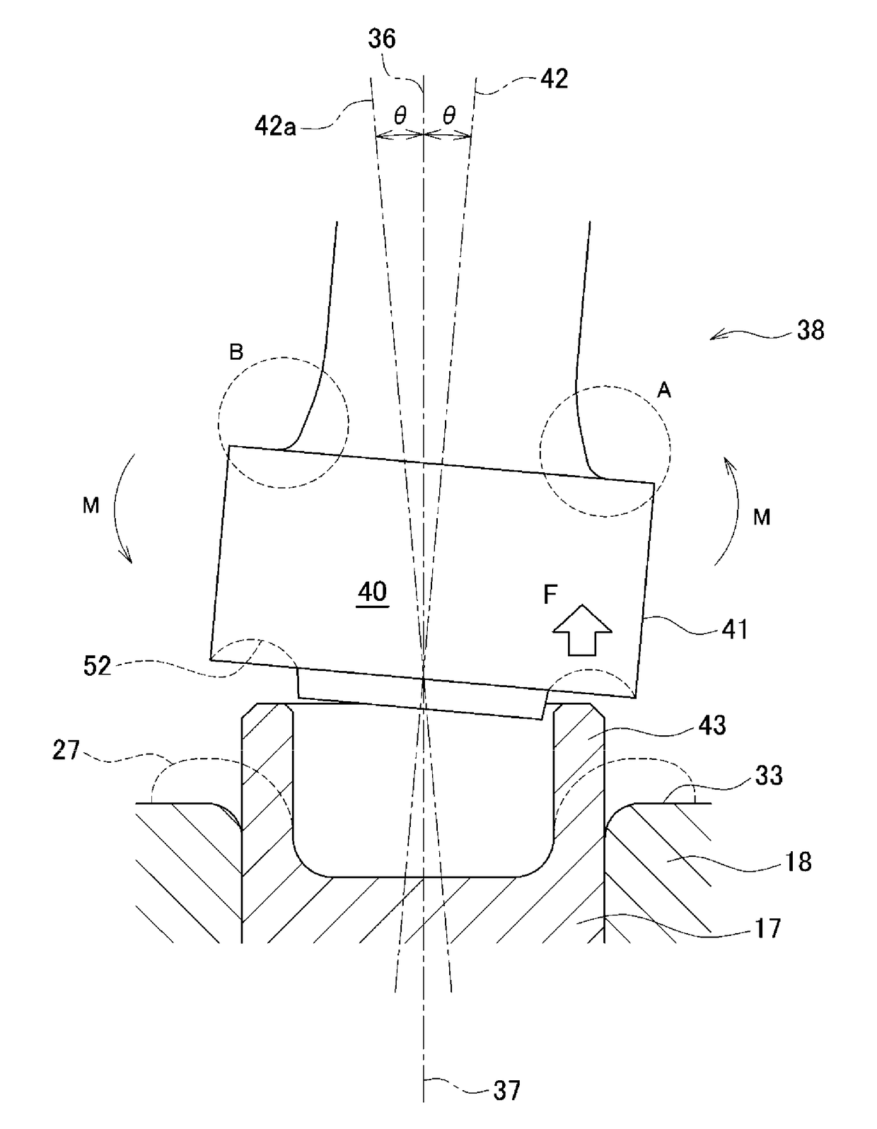
When the oscillating clinching apparatus 100 with the main spindle 105 assembled therein is used as a mass production facility to manufacture a large number of hub units, the “joint portion” K may disadvantageously be broken relatively prematurely.

Method used


Image

  • Hub unit manufacturing apparatus
  • Hub unit manufacturing apparatus
  • Hub unit manufacturing apparatus

Examples


first embodiment

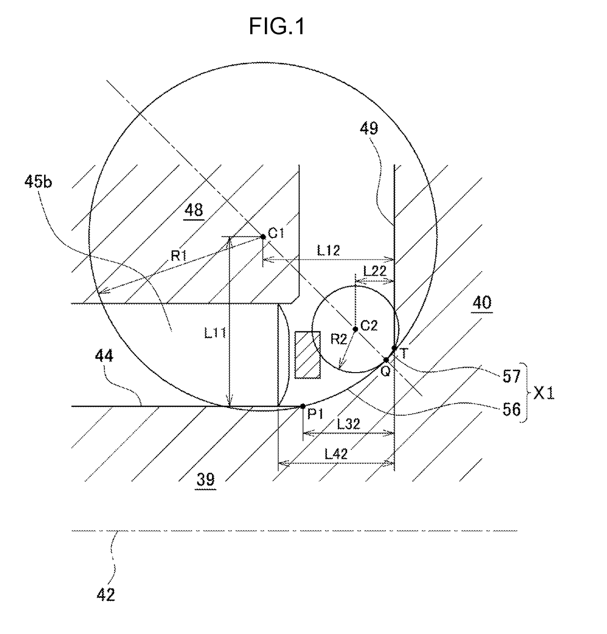
[0041]An axial section of the portion where the outer peripheral surface 44 and the side surface 49 are joined together is shaped by a first circular arc 56 joined to the outer peripheral surface 44 and a second circular arc 57 joined to the side surface 49. An area that joins the outer peripheral surface 44 and the side surface 49 together is hereinafter referred to as a “continuous portion”. In a first embodiment, an area formed of the first circular arc 56 and the second circular arc 57 is referred to as a continuous portion X1.

[0042]The first circular arc 56 is shaped to protrude inward in the radial direction. A curvature center C1 of the first circular arc 56 is located outward of the outer peripheral surface 44 in the radial direction and closer to the outer peripheral surface 44 than to the side surface 49. The first circular arc 56 intersects or contacts the outer peripheral surface 44, and an extension of the first circular arc 56 intersects the side surface 49. That is, w...

second embodiment

[0069]In the second embodiment, a high stress is generated at a portion corresponding to the second circular arc 64. As a result, stress generated at the portion corresponding to the first circular arc 63 is distributed to enable the maximum value of stress generated at the continuous portion X2 to be reduced to an acceptable level compared to the fatigue strength of the material.

[0070]However, the stress generated at the portion corresponding to the first circular arc 63 is slightly higher than the stress in the first embodiment. This is because the curvature radius of the second circular arc 64, which is larger than the curvature radius of the second circular arc 57 in the first embodiment, serves to reduce the stress generated at the portion corresponding to the second circular arc 64, and thus the effect of distributing the stress generated on the first circular arc 63 is reduced.

[0071]Therefore, to distribute the stress on the first circular arc 63, it is appropriate to set the...


PUM

PropertyMeasurementUnit
curvature radius R2aaaaaaaaaa
thicknessaaaaaaaaaa

Abstract

An axial section of a continuous portion where an outer peripheral surface of a spindle portion of a main spindle in which a punch is installed is continuous with an outer peripheral surface of a punch holder is formed of a first circular arc joined to the outer peripheral surface of the spindle portion and a second circular arc joined to the outer peripheral surface of the punch holder. The first circular arc and the second circular arc are in contact with each other. The second circular arc is smaller than the first circular arc in curvature radius.

Description

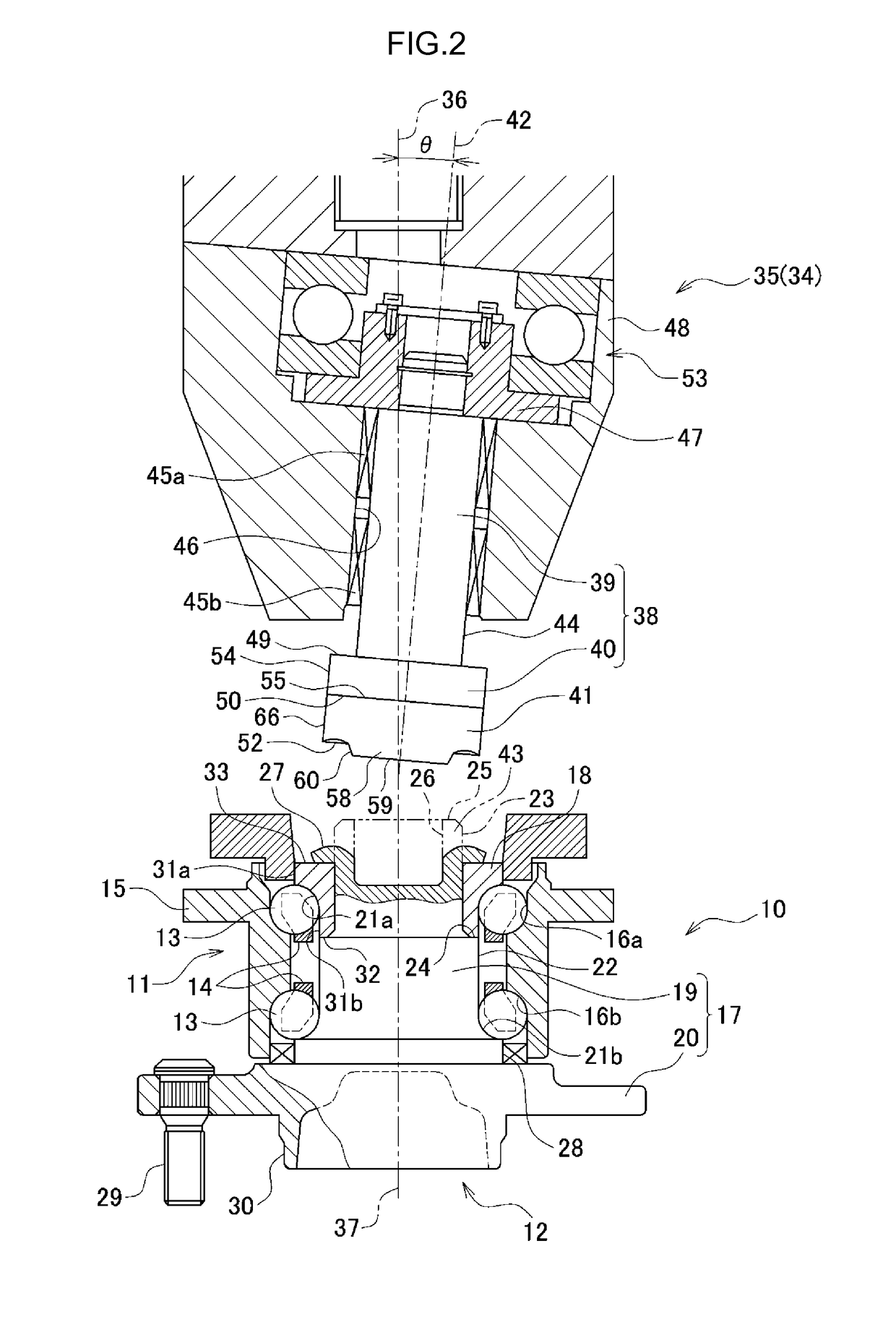
INCORPORATION BY REFERENCE[0001]The disclosure of Japanese Patent Application No. 2014-187166 filed on Sep. 15, 2014 including the specification, drawings and abstract, is incorporated herein by reference in its entirety.BACKGROUND OF THE INVENTION[0002]1. Field of the Invention[0003]The present invention relates to a manufacturing apparatus that manufactures a hub unit and that is used in a process of clinching a shaft end of an inner shaft after an inner ring member is press-fitted over the shaft end of the inner shaft. In particular, the present invention relates to a manufacturing apparatus in which a main spindle supporting a clinching punch has an improved strength.[0004]2. Description of Related Art[0005]A hub unit is used as a bearing apparatus that supports wheels of a vehicle such that the wheels are rotatable. In an inner shaft of the hub unit, an inner ring member is assembled into a shaft end of a hub shaft. During a process of manufacturing a hub unit, the shaft end of...

Claims


Application Information

Patent Timeline
Patent Type & Authority Patents(United States)
IPC IPC(8): B23P11/00B60B27/00
CPCB23P11/005B60B27/0031B60B27/0084B60B2310/206Y10T29/49845Y10T29/49533Y10T29/49535Y10T29/49536Y10T29/49833B60B2310/213B21J9/025B21K25/00
Inventor ONIZUKA, TAKAAKI
Owner JTEKT CORP
Learn More