
Control apparatus for hybrid vehicle

a control apparatus and hybrid technology, applied in the direction of battery/fuel cell control arrangement, engine-driven generators, transportation and packaging, etc., can solve the problems of low engine operation efficiency, deterioration of fuel consumption, and inability to increase the remaining amount of charge so

Active Publication Date: 2018-10-23
TOYOTA JIDOSHA KK
View PDF47 Cites 2 Cited by
  • Summary
  • Abstract
  • Description
  • Claims
  • Application Information

AI Technical Summary

Benefits of technology

The patent text describes a control system for hybrid vehicles that prevents a decrease in fuel efficiency during downhill control or traffic congestion control. The system uses the remaining amount of battery charge to determine the amount of electric power needed and adjusts the engine output power accordingly to increase or decrease the remaining battery charge. This prevents deterioration of fuel efficiency when the vehicle is traveling on specific traffic congestion sections, resulting in better fuel efficiency and a better driving experience for the driver. The system also avoids the abrupt increase or decrease in battery charge during traffic congestion control, which can cause discomfort to the driver.

Problems solved by technology

However, if a downhill section is long, the remaining amount of charge SOC reaches the upper limit remaining amount of charge, so it is not possible to increase the remaining amount of charge SOC any more.
Generally, when the output power of the engine is small, the operation efficiency of the engine is low.
In this way, if the remaining amount of charge SOC decreases in the case where the vehicle travels on a traffic congestion section and, as a result, the remaining amount of charge SOC reaches the lower limit remaining amount of charge, it is necessary to carry out forcible charging by using the output power of the engine, so there is a concern that the fuel consumption deteriorates.
Therefore, the remaining amount of charge excessively decreases, with the result that forcible charging is performed and there is a concern that the fuel consumption deteriorates on the contrary.
On the other hand, for example, if the vehicle is traveling on a traffic congestion section at the time when the remaining amount of charge is intended to be increased by increasing the target remaining amount of charge in preparation for a traffic congestion section, the frequency at which the engine is operated in a low load state having a low operation efficiency is increased in an attempt to increase the remaining amount of charge, and there is a concern that the fuel consumption deteriorates on the contrary.
With the apparatus, even when a traffic congestion section is included in the scheduled travel route of the vehicle, there is a high possibility that deterioration of fuel consumption is suppressed through traffic congestion control.
When the remaining amount of charge reaches the lower limit remaining amount of charge, it is required to increase the amount of electric power that is generated by the electric motor by increasing the output power of the engine, so the fuel consumption of the vehicle deteriorates.
Therefore, the amount of electric power that is generated by using the output power of the engine is increased, with the result that the fuel consumption of the vehicle deteriorates.
On the other hand, the apparatus does not execute traffic congestion control when the distance from the end of traveling on the specific traffic congestion section to entry into the target traffic congestion section is short.

Method used


Image

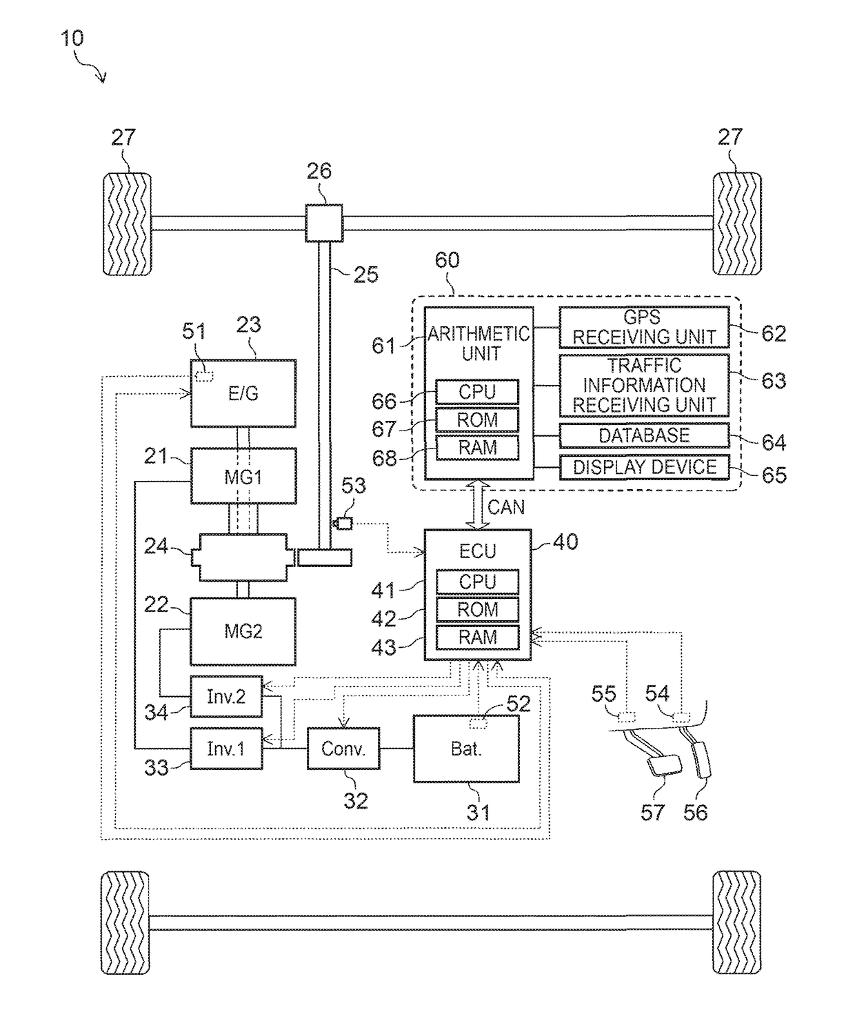
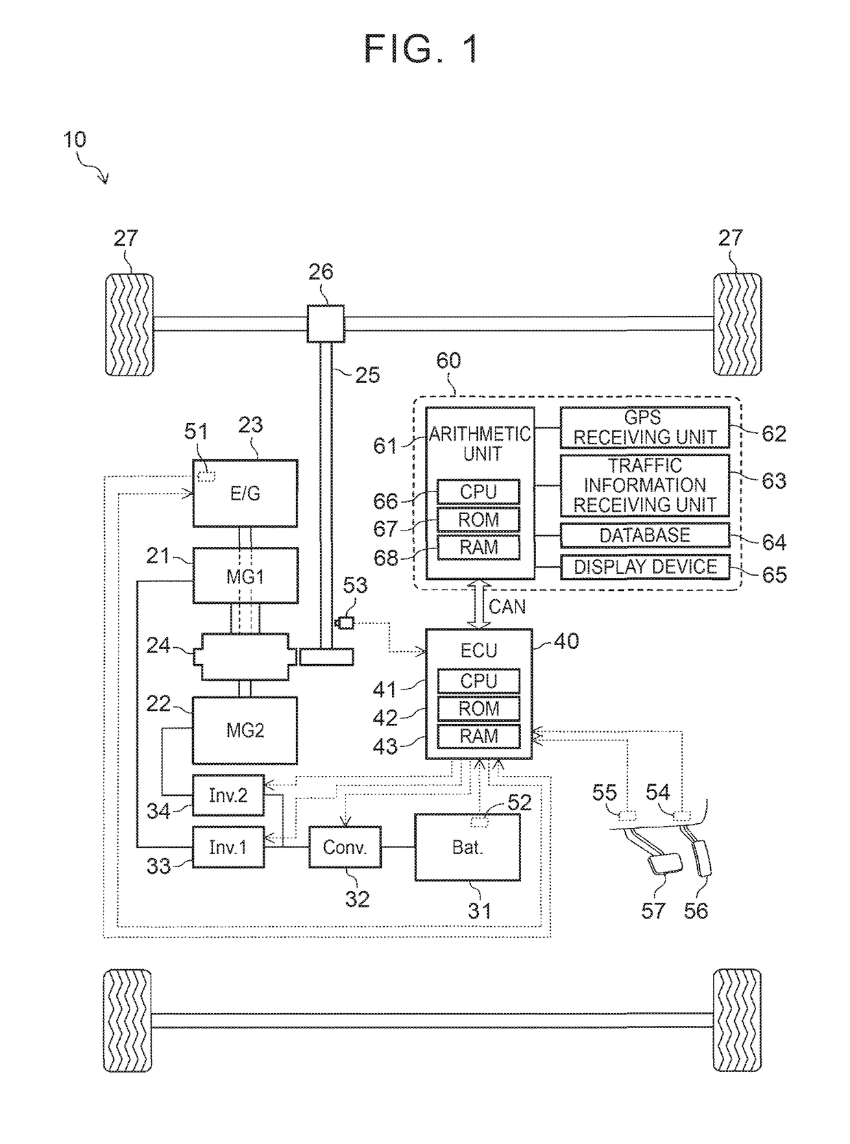
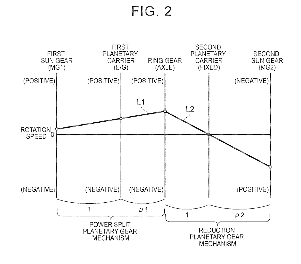
  • Control apparatus for hybrid vehicle
  • Control apparatus for hybrid vehicle
  • Control apparatus for hybrid vehicle

Examples


case 1

th

[0130]In the case where the required engine output power Pe* is larger than the output power threshold Peth, the CPU makes an affirmative determination in step 720, proceeds to step 725, and determines whether the engine 23 is stopped at the current point in time. When the engine 23 is stopped, the CPU makes an affirmative determination in step 725, proceeds to step 730, and executes the process of starting the operation of the engine 23. Subsequently, the CPU proceeds to step 735. In contrast, when the engine 23 is in operation, the CPU makes a negative determination in step 725, and directly proceeds to step 735.

[0131]The CPU sequentially executes the processes of step 735 to step 760 described below. After that, the CPU proceeds to step 795, and once ends the routine.

[0132]In step 735, the CPU determines a target engine rotation speed Ne* and a target engine torque Te* such that the output power equal to the required engine output power Pe* is output from the engine 23 and the ...

case 2

th

[0138]In the case where the required engine output power Pe* is smaller than or equal to the output power threshold Peth, when the CPU proceeds to step 720, the CPU makes a negative determination in step 720, proceeds to step 765, and determines whether the engine 23 is in operation at the current point in time.

[0139]When the engine 23 is in operation, the CPU makes an affirmative determination in step 765, proceeds to step 770, executes the process of stopping the operation of the engine 23, and then proceeds to step 775. In contrast, when the engine 23 is stopped, the CPU makes a negative determination in step 765, and directly proceeds to step 775.

[0140]In step 775, the CPU sets the value of the target MG1 torque Tm1* to zero. In addition, the CPU proceeds to step 780, and calculates the target MG2 torque Tm2* that is a torque that should be generated by the second electric motor 22 in order to bring the torque that acts on the ring gear into coincidence with the required ring ...


PUM


Abstract

A control apparatus that is applied to a vehicle includes a control unit. The control unit is configured to, when the vehicle is traveling on a specific traffic congestion section at a time when the vehicle has reached a downhill control start point or a traffic congestion control start point, not start any of a downhill control and a traffic congestion control. After the vehicle travels on the specific traffic congestion section, the downhill control or the traffic congestion control is started only when an effect of improvement in fuel consumption resulting from the downhill control or the traffic congestion control is expected.

Description

CROSS-REFERENCE TO RELATED APPLICATIONS[0001]This application is based upon and claims the benefit of priority from Japanese Patent Application No. 2015-145353, filed on Jul. 22, 2015, the entire contents of which are incorporated herein by reference in entirety.BACKGROUND OF THE DISCLOSURE[0002]1. Field of the Disclosure[0003]The present application relates to a control apparatus for a hybrid vehicle including both an internal combustion engine and an electric motor as drive sources of the vehicle.[0004]2. Description of Related Art[0005]There is known a hybrid vehicle (hereinafter, also simply referred to as vehicle) including both an internal combustion engine (hereinafter, also simply referred to as engine) and an electric motor as drive sources of the vehicle. The vehicle includes a storage battery. The storage battery supplies electric power to the electric motor, and is charged by using the output power of the engine.[0006]In addition, when the rotation of an axle is transmit...

Claims


Application Information

Patent Timeline
Patent Type & Authority Patents(United States)
IPC IPC(8): B60W20/12B60W50/00B60L15/20B60W10/26B60L11/18B60W20/14B60L7/18B60W10/06B60W10/08B60K6/445B60W30/18B60L50/16
CPCB60W20/12B60L7/18B60L11/1861B60L15/2045B60W10/06B60W10/08B60W10/26B60W20/14B60W30/18018B60W30/18127B60W50/0097B60K6/445Y02T90/16B60L2240/642B60W2550/142B60W2550/143B60W2550/20B60W2550/402B60W2710/244Y02T10/6239Y02T10/6291Y02T10/645Y02T10/705Y02T10/7005Y02T10/7044Y02T10/72Y02T10/7283Y02T10/7291B60W10/18B60W2556/45B60W2554/00B60W2552/15B60W2552/20B60W2556/50B60L58/15Y02T10/62Y02T10/64Y02T10/70
Inventor OGAWA, YUKI
Owner TOYOTA JIDOSHA KK
Learn More