Method of operating aircraft drive to move an aircraft under adverse ground conditions

a technology of aircraft drive and aircraft, which is applied in the direction of energy-saving operation measures, alighting gear, transportation and packaging, etc., can solve the problems of aircraft tires becoming stuck to the runway surface, runway deterioration, and runway surface deformation

Active Publication Date: 2018-10-23
BOREALIS TECH LTD
View PDF53 Cites 1 Cited by
  • Summary
  • Abstract
  • Description
  • Claims
  • Application Information

AI Technical Summary

Benefits of technology

[0010]It is a primary object of the present invention, therefore, to provide a method for operating a powered self-propelled aircraft drive wheel under adverse runway conditions which have caused one or more of the aircraft's tires to adhere directly or indirectly to the tarmac that employs the powered self-propelled drive wheel to release the aircraft tire and enable the aircraft to move.
[0011]It is another object of the present invention to provide a method for using a powered self-propelled aircraft drive wheel to effectively free an aircraft wheel tire that has become stuck directly or indirectly to the tarmac without increasing the size of the wheel driver.
[0012]It is a further object of the present invention to provide a method for releasing one or more aircraft tires stuck to the tarmac or to ice on the tarmac that uses the aircraft's steering in conjunction with the aircraft's powered self-propelled wheel driver to release a stuck tire.
[0014]It is yet a further object of the present invention to provide a method for utilizing the driver from a powered self-propelled aircraft drive wheel to release stuck aircraft tires that will not otherwise move under direct aircraft pressure.

Problems solved by technology

The presence of moisture, whether from rain, slush, snow, or ice, however, is a major factor in the degradation of runway surfaces.
Aircraft tires may also become stuck to the runway surface under adverse ground conditions.
The factors mentioned above all contribute to runway deterioration and decrease the coefficient of friction, affecting aircraft braking and landing distance.
This can lead to a situation in which the frictional forces between the tire and the runway cannot be overcome by direct aircraft pressure, resulting in a stuck aircraft with one or more tires adhered to the runway surface.
When an aircraft is completely stopped and at rest on the ground, there are numerous factors in addition to friction characteristics that can make movement of the aircraft from this resting condition difficult, particularly in cold weather.
For example, tires that are cold tend to become misshapen, making them harder to turn.
Aircraft tires can also become stuck to the tarmac when water freezes between the tire and the tarmac or through light adhesion between the tire and tarmac in drier conditions.
In inclement weather, especially when the temperatures are around freezing, the likelihood of ice forming between one of more of the aircraft tires and the tarmac can be quite high, causing the tires and, hence, the wheels to become stuck to the tarmac.
Stommel, however, does not even remotely suggest that this system would be effective or could be used in snow, ice, or other conditions to release an aircraft tire that has become stuck, directly or indirectly, to the travel surface.
An aircraft with one or more tires immobilized by ice presents challenges during push back when a tow vehicle or tug is used.
These systems, however, are functionally required to be small and lightweight and cannot apply the same force as a tug to free aircraft wheels stuck in ice.
Increasing the size of the driver in a powered self-propelled aircraft wheel to provide more force directly to the wheel to overcome ice adhesion is not a viable solution because these systems must remain as small and lightweight as possible, in part to fit within the space allotted for an aircraft's landing gear.
The prior art has not provided a method for operating a powered self-propelled aircraft drive wheel under adverse runway conditions which have caused one or more of the aircraft's tires to adhere directly or indirectly to the tarmac that employs the powered self-propelled drive wheel to release the aircraft tires and enable the aircraft to move.

Method used


Image

  • Method of operating aircraft drive to move an aircraft under adverse ground conditions
  • Method of operating aircraft drive to move an aircraft under adverse ground conditions

Examples


Embodiment Construction

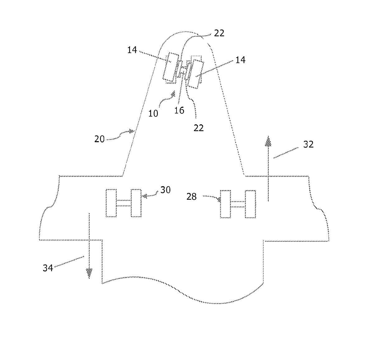
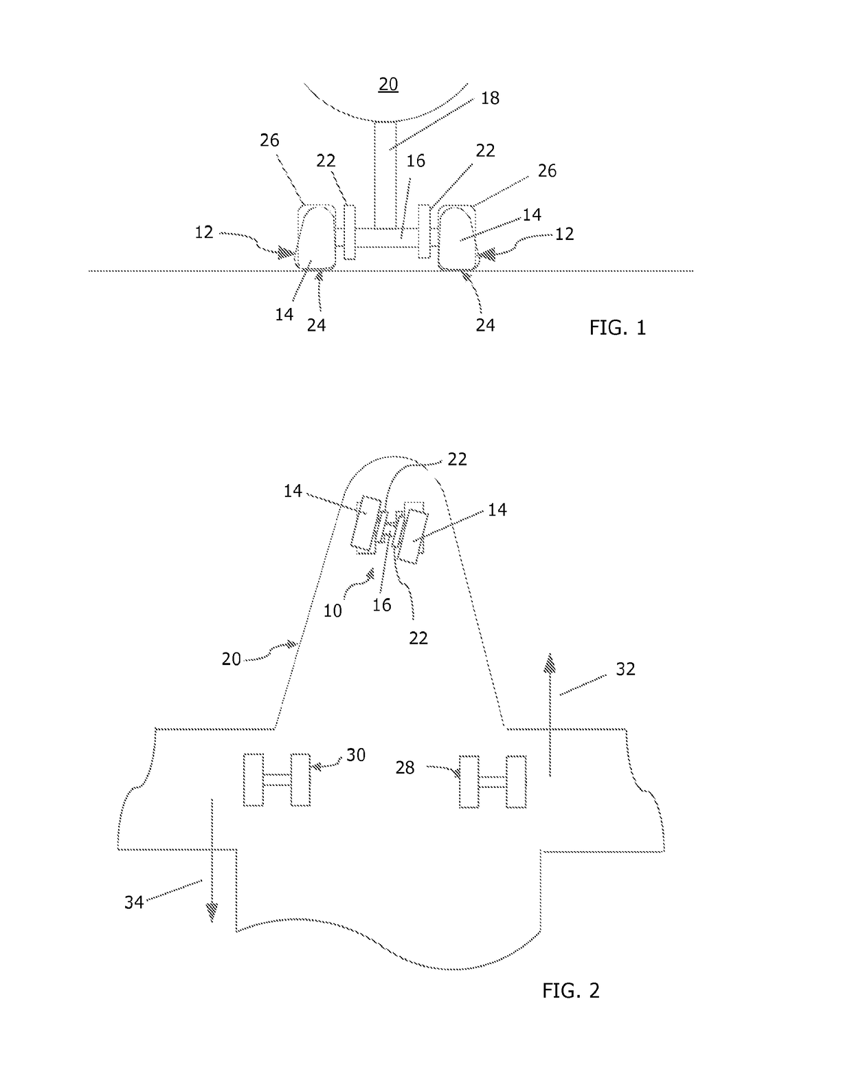
[0019]A powered self-propelled nose wheel or other powered aircraft drive wheel is uniquely positioned to maneuver an aircraft in a variety of circumstances on the ground without assistance from external vehicles. The driver for the powered drive wheel optimally exerts sufficient power to move the aircraft at runway speeds, and its small size enables the driver to fit within the landing gear space. When weather conditions and, hence, runway conditions are adverse, particularly when the weather is cold, icy, or snowy, it is not unusual for aircraft tires to adhere either directly to the tarmac or to ice formed by water freezing between the tire and tarmac surface. The method of the present invention uses a powered self-propelled nose wheel or other wheel driver in conjunction with the aircraft steering and, when indicated, the aircraft brakes to apply enough force to a stuck tire to release it from its stuck position, thereby enabling the aircraft to move on the ground in a desired d...


PUM


Abstract

A method is provided for restoring mobility to an aircraft equipped with at least one self-propelled drive wheel powered by a driver when the aircraft has been rendered immobile as a result of one or more wheel tires adhering to and becoming stuck to tarmac or another ground surface. The method uses forces generated by the cooperative action of the wheel driver, the aircraft steering, and the aircraft braking system to release adherent tires of each set of main wheels and / or nose gear wheels by applying differential force to one set of wheels at a time to release any adherent tires so that the aircraft is able to move on the ground surface and travel in a desired direction at a desired speed.

Description

PRIORITY[0001]This application claims priority from U.S. Provisional Patent Application No. 61 / 439,579, filed Feb. 4, 2011, the disclosure of which is fully incorporated herein.TECHNICAL INVENTION[0002]The present invention relates generally to the operation of aircraft on the ground under adverse ground conditions and specifically to a method of moving, under adverse ground conditions, an aircraft equipped with a powered self-propelled drive wheel from a position where the aircraft is temporarily immobile to full mobility and movement.BACKGROUND OF THE INVENTION[0003]Arriving and departing aircraft must travel on the ground between landing and subsequent takeoff along runways and taxiways associated with an airport. Over time, the tarmac surface of a runway or taxiway can change as a result of rubber buildup from the application of aircraft brakes, paint used for marking, chemicals, and erosion of the tarmac material. These changes in the runway surface produce changes in the frict...

Claims


Application Information

Patent Timeline
Patent Type & Authority Patents(United States)
IPC IPC(8): B64C25/40
CPCB64C25/405Y02T50/823Y02T50/80
Inventor EDELSON, JONATHAN S.COX, ISAIAH W.GILLERAN, NEALPERKINS, SCOTT
Owner BOREALIS TECH LTD
Why Eureka
Try Eureka