Rechargeable battery pack having a contact plate for connection to a load

a rechargeable battery and load technology, applied in the field of rechargeable battery packs, can solve the problems of poor contact formation, increased contact wear under electrical loading, and increased temperature of individual cells and electrical connections,

Active Publication Date: 2018-10-23
ANDREAS STIHL AG & CO KG
View PDF4 Cites 0 Cited by
  • Summary
  • Abstract
  • Description
  • Claims
  • Application Information

AI Technical Summary

Benefits of technology

[0007]A mount for the contact plate is provided on one side face of the cell holder, wherein the contact plate is mounted so as to be displaceable in a displacement direction in the mount. The electrical connection between the individual cell or a cell assembly and the contact plate is formed by at least one elastic contact strip which is embodied so as to be resilient in sprung fashion in the displacement direction of the contact plate. The contact plate is held by the elastic contact strip, wherein the contact plate remains displaceable relative to the longitudinal axis of the contact strips. This ensures that the contact plate becomes aligned with its plug-type connections with the connection contacts in a rechargeable battery holder of an implement and that a mechanically secure connection is formed, which ensures safe conduction of current even under high electrical loading. A contact strip which heats up under electrical loading and possibly occurring changes in length can also be compensated by the contact strip itself. The elastic contact strip itself serves here as a resilient connection element, and the contact plate therefore continues to be displaceable.
[0008]The displaceability of the contact plate ensures, in particular, that when making contact with corresponding connection contacts, for example in a rechargeable battery shaft, the contact plate can align itself—with a spring effect of the elastic contact strips—with the connection elements of the rechargeable battery shaft, ensuring that contact is formed in a simple, electrically loadable fashion.
[0020]In one simple embodiment of this independent concept of a fuse element, a recess is provided in the contact strip, between the contact end and the connection lug. This recess is arranged near to a longitudinal edge of the contact strip in such a way that the recess bounds, with a longitudinal edge of the contact strip, a material web which forms the weakened material portion of the contact strip, and therefore forms the fuse element. If in each case a recess is formed on both sides of the longitudinal central axis in the contact strip, it can be expedient to connect the recesses to one another via a longitudinal slot. In a side view of the contact strip, the recesses and the longitudinal slot connecting them have approximately the shape of a letter Z, wherein the one recess forms the foot of the letter Z, and the other recess the top of the letter Z. This physical embodiment maintains the mechanical stability of the contact strip, since the weakened material portion of the contact strip is distributed over the length thereof.

Problems solved by technology

If the connection contacts and the plug-type connections do not fit one another, poor contacts may be formed.
If there are also vibrations caused by the implement, the connection contacts may lift off the plug-type connections, which can lead to increased contact wear under electrical loading.
A high power drain from the rechargeable battery pack can also lead to an increase in temperature of the individual cells and of the electrical connections, as a result of which the position of the contact plate may change.

Method used


Image

  • Rechargeable battery pack having a contact plate for connection to a load
  • Rechargeable battery pack having a contact plate for connection to a load
  • Rechargeable battery pack having a contact plate for connection to a load

Examples


Embodiment Construction

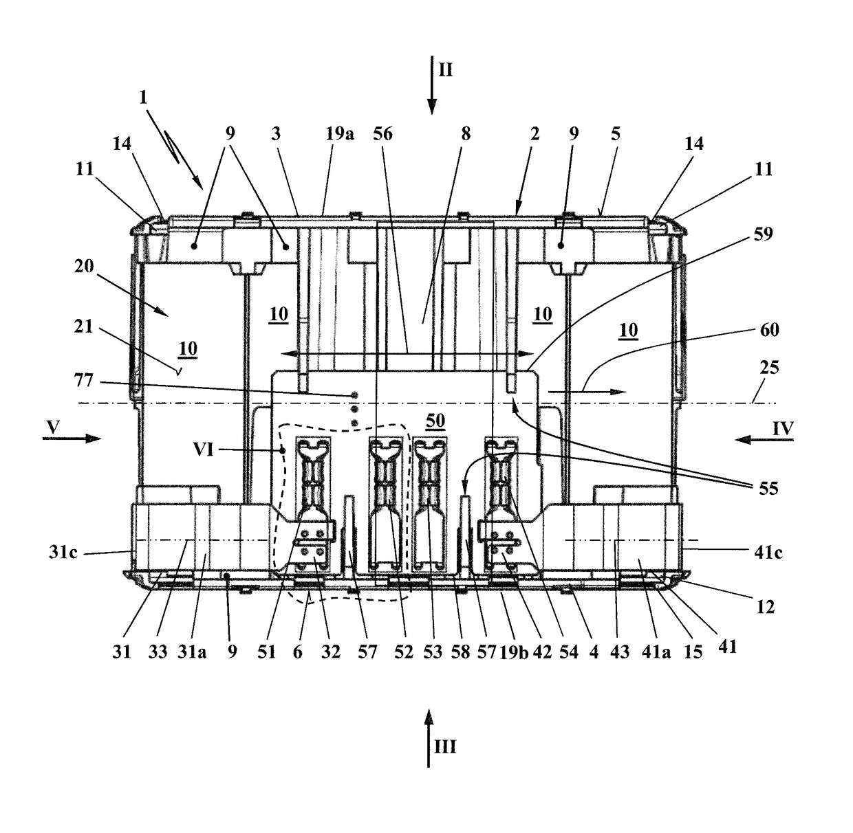
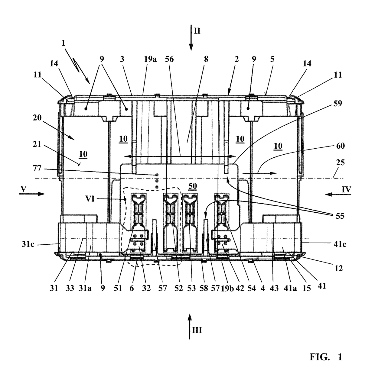
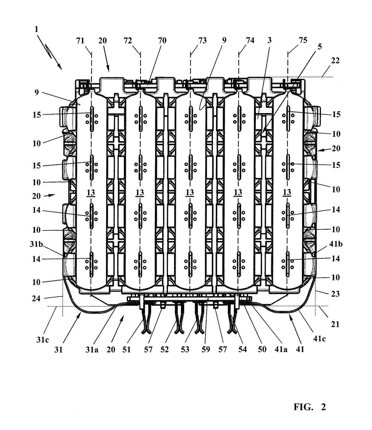
[0030]The rechargeable battery pack 1 illustrated in FIG. 1 includes a cell holder 2 and at least one individual cell 10 which as a cylindrical base shape. In this embodiment, a plurality of individual cells 10 are combined to form a rechargeable battery pack 1. In each case one end 11 of an individual cell 10 forms a positive pole 14; another end 12, lying opposite, of the individual cell 10 forms a negative pole 15. The cell holder 2 is assembled from a first, upper cell trough 3 and a second, lower cell trough 4. The first, upper cell trough 3 forms a first, upper end side 5 of the rechargeable battery pack 1. The second, lower cell trough 4 forms a second, lower end side 6 of the rechargeable battery pack 1. The ends 11 and 12 of the individual cells 10 are held in assigned receptacles 9 in the cell troughs (3, 4). The one ends 11 of the individual cells 10 lie on a common, first contact side 19a of the cell holder 2. The other ends 12 of the individual cells 10 lie on a common,...


PUM

PropertyMeasurementUnit
angleaaaaaaaaaa
anglesaaaaaaaaaa
curve angleaaaaaaaaaa

Abstract

A rechargeable battery pack includes at least one individual cell which is accommodated in a cell holder and is in electrical contact on a contact side via a cell connector. An electric load is to be connected via a contact plate which has a plurality of plug-type connections, wherein the contact plate is located on one side face of the cell holder. In order to compensate positional tolerances between the plug-type connections of the contact plate and external connection contacts, a mount for the contact plate is provided on one side face of the cell holder, in which mount the contact plate is mounted so as to be displaceable in a displacement direction. The electrical connection between the individual cell and the contact plate is embodied by an elastic contact strip, wherein the contact strip is embodied so as to be resilient in a sprung fashion in the displacement direction of the contact plate.

Description

CROSS REFERENCE TO RELATED APPLICATION[0001]This application claims priority of German patent application no. 10 2014 018 474.9, filed Dec. 12, 2014, the entire content of which is incorporated herein by reference.BACKGROUND OF THE INVENTION[0002]Known rechargeable battery packs are usually made of an arrangement of a plurality of individual cells which are electrically connected to one another via cell connectors on one contact side in each case to form a cell assembly. The individual cells of the rechargeable battery pack are connected to an electric load via a contact plate which has a plurality of plug-type connections. The contact plate can be located on a side face of the cell holder.[0003]Rechargeable battery packs of this type are, for example, inserted into holders of electrical implements in which connection contacts are provided which are aligned in the insertion direction and engage in the plug-type connections of the contact plate. When contact is made, it is necessary ...

Claims


Application Information

Patent Timeline
Patent Type & Authority Patents(United States)
IPC IPC(8): H01M2/10H01M10/42H01M2/30H01M2/34H01M50/528H01M50/213H01M50/264H01M50/296H01M50/503H01M50/512
CPCH01M2/30H01M2/10H01M2/348H01M10/425H01M2/1016H01M2200/103H01M50/296H01M50/503H01M50/512H01M50/264H01M50/213Y02E60/10H01M50/581
Inventor GAUL, HENRIKLIEBHARD, GERNOTWAGNER, DANIELSCHURR, MARTIN
Owner ANDREAS STIHL AG & CO KG
Why Eureka
Try Eureka