
Zone control system

a control system and control panel technology, applied in the direction of substation equipment, electrical equipment, connection management, etc., to achieve the effects of low manufacturing cost, convenient and efficient use, and durable and reliable construction

Active Publication Date: 2018-10-23
KINGRY FREDERIC KELLY
View PDF6 Cites 1 Cited by
  • Summary
  • Abstract
  • Description
  • Claims
  • Application Information

AI Technical Summary

Benefits of technology

The present invention provides a new and improved zone control system that can be easily and efficiently used, manufactured, and marketed. The system is durable and reliable, and can be susceptible of a low cost of manufacture and sale to the consuming public. Additionally, the system can be used to establish an operational controlled zone in which digital wireless devices should not be used and precluded in a safe, convenient, and economical manner. The system can be used in personal, corporate, educational, and vehicle settings.

Problems solved by technology

While these devices fulfill their respective, particular objectives and requirements, the aforementioned patents do not describe a zone control system that allows establishing an operational controlled zone in which digital wireless devices should not be used and for precluding unwanted usage of digital wireless devices in the operational controlled zone, the establishing and precluding being done in a safe, convenient, and economical manner.

Method used


Image

  • Zone control system
  • Zone control system
  • Zone control system

Examples


Embodiment Construction

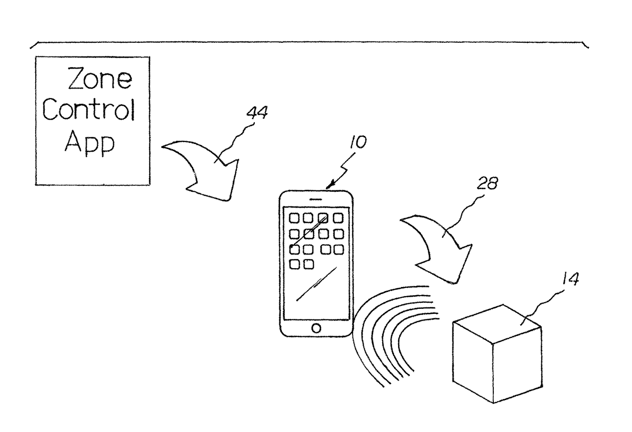
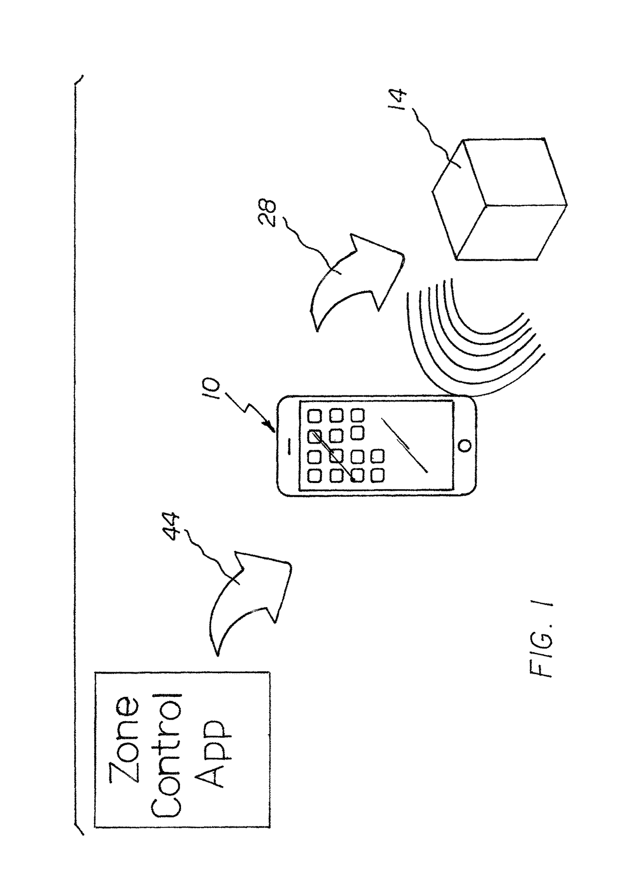
[0024]With reference now to the drawings, and in particular to FIG. 1 thereof, the preferred embodiment of the new and improved zone control system embodying the principles and concepts of the present invention and generally designated by the reference numeral 10 will be described.

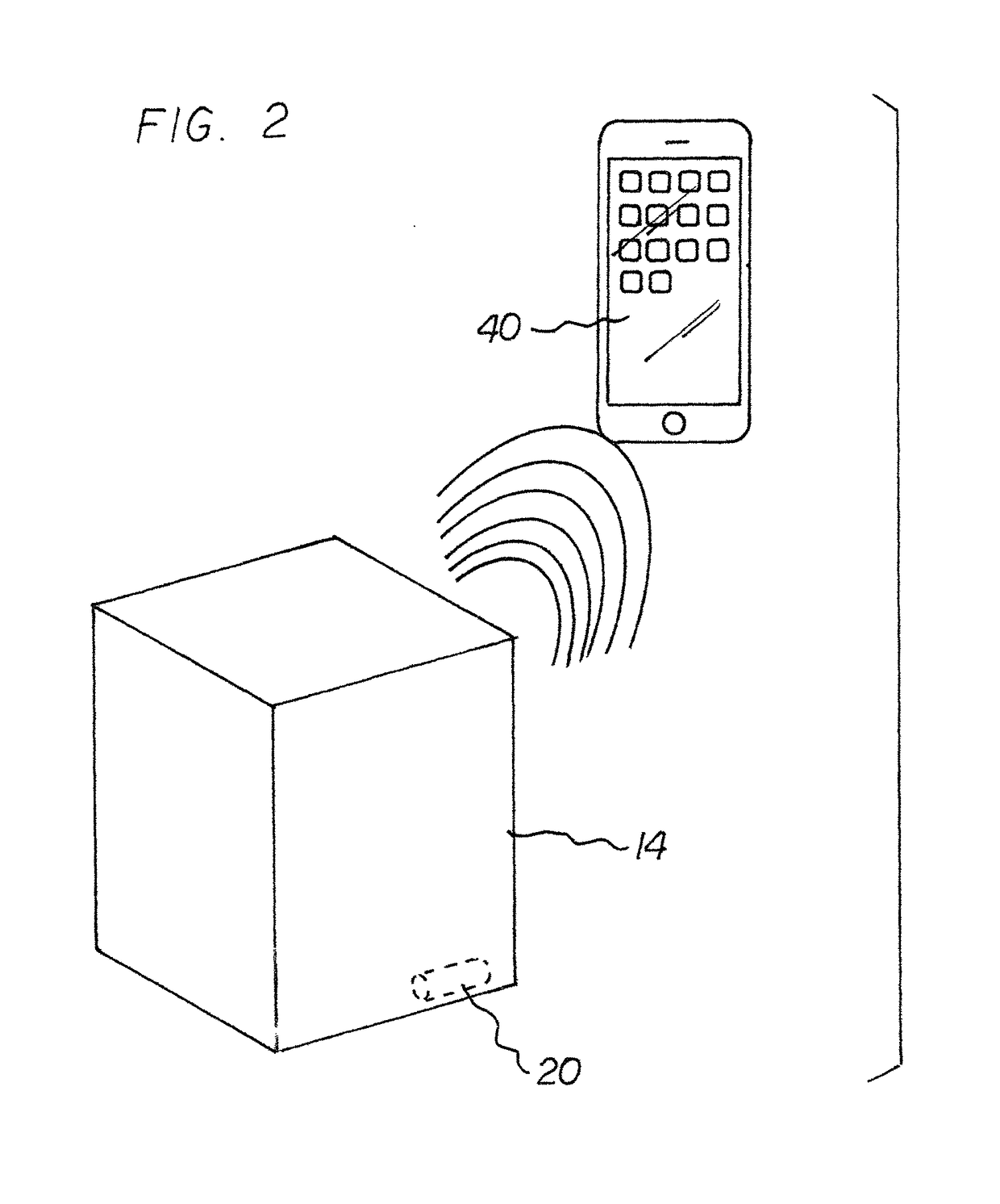
[0025]The present invention, the zone control system 10 is comprised of a plurality of components. In their broadest context such include a control box, control box hardware, a primary printed circuit board, software, a digital wireless device, digital wireless device hardware, and a secondary printed circuit board. Such components are individually configured and correlated with respect to each other so as to attain the desired objective.

[0026]From a specific standpoint, in the preferred embodiment of the zone control system, designated by reference numeral 10, first provided is a control box 14 having, but not limited to, a cubical configuration. The control box has an exterior and an interior.

[0027]Next ...


PUM


Abstract

A control box with control box hardware has an ON operative orientation. A primary printed circuit board has primary software operative in response to the orientation. The primary software when in the operational orientation functions to disseminate a blocking / filtering signals within a predetermined operational controlled zone. A digital wireless device performs normal digital wireless device functions. Digital wireless device hardware functions for switching between an inoperative orientation and an operative orientation. A secondary printed circuit board / software has secondary software operative to switch to the inoperative orientation in response to the digital wireless device entering the operational controlled zone to preclude the digital wireless device from performing normal digital wireless device functions.

Description

BACKGROUND OF THE INVENTIONRelated Application[0001]This application is based upon Provisional Application No. 62 / 268,156 filed Dec. 16, 2015, the priority of which is claimed and the subject matter of which is incorporated herein by reference.Field of the Invention[0002]The present invention relates to a zone control system and more particularly pertains to establishing an operational controlled zone in which digital wireless devices should not be used and for precluding unwanted usage of digital wireless devices in the operational controlled zone, the establishing and precluding being done in a safe, convenient, and economical manner. The system functions in special environments including personal, corporate, educational, and vehicle.Description of the Prior Art[0003]The use of zone control systems of known designs and configurations is known in the prior art. More specifically, zone control systems of known designs and configurations previously devised and utilized for the purpos...

Claims


Application Information

Patent Timeline
IPC IPC(8): H04W24/00H04M3/00H04M1/725H04W76/20H04W88/02H04M1/72463
CPCH04M1/72577H04W76/20H04W88/02H04M1/715H04M1/72463
Inventor KINGRY, FREDERIC KELLY
Owner KINGRY FREDERIC KELLY
Learn More