
System arrangement of lifting mechanisms and method of operating the system arrangement

a technology of system arrangement and lifting mechanism, which is applied in the direction of winding mechanism, hoisting equipment, etc., can solve the problems of automatic closing of braking circuit, serious transmission damage, and inability to adjust safety brakes for high switching cycles

Active Publication Date: 2018-10-30
M A T MALMEDIE ANTRIEBSTECHN
View PDF16 Cites 3 Cited by
  • Summary
  • Abstract
  • Description
  • Claims
  • Application Information

AI Technical Summary

Benefits of technology

The patent describes a transmission that has a safety mechanism called a freewheel. This freewheel prevents damage to the transmission or other components when the load is lowered. The brakes used for this lowering mode act on the rotating masses, which then rotate freely through the freewheel. The result is that the braking travel of the load is curtailed, as no accelerating masses have to be braked. Overall, this safety mechanism prevents damage and ensures the load can be safely lowered without causing any harm to the transmission.

Problems solved by technology

In the event of a power failure or an emergency shutdown, that has the result that the braking circuits are automatically closed.
In accordance with the status at the present time the safety brakes are not suitable for high switching cycles and consequently close only in the event of transmission breakdown, power failure, emergency shutdown and the like.
However a number of problems arise due to the two braking circuits which are implemented in an emergency situation.
Those problems can lead to serious transmission damage, in particular in the case of crane lifting mechanisms with particularly frequent shutdown situations and involving high lifting speeds.
In addition, due to the operation of both braking circuits, inevitable ‘over-brakings’ of the lifting mechanism occur, with the resultant negative effects on the statics and other crane components.

Method used


Image

  • System arrangement of lifting mechanisms and method of operating the system arrangement
  • System arrangement of lifting mechanisms and method of operating the system arrangement
  • System arrangement of lifting mechanisms and method of operating the system arrangement

Examples


Embodiment Construction

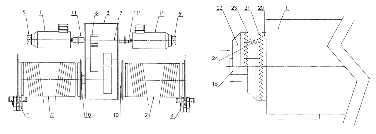
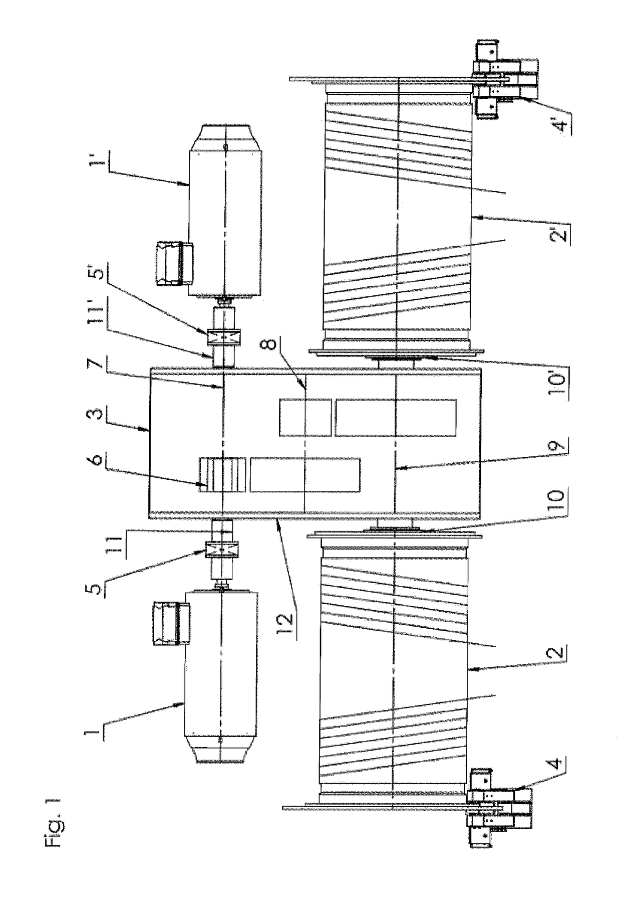
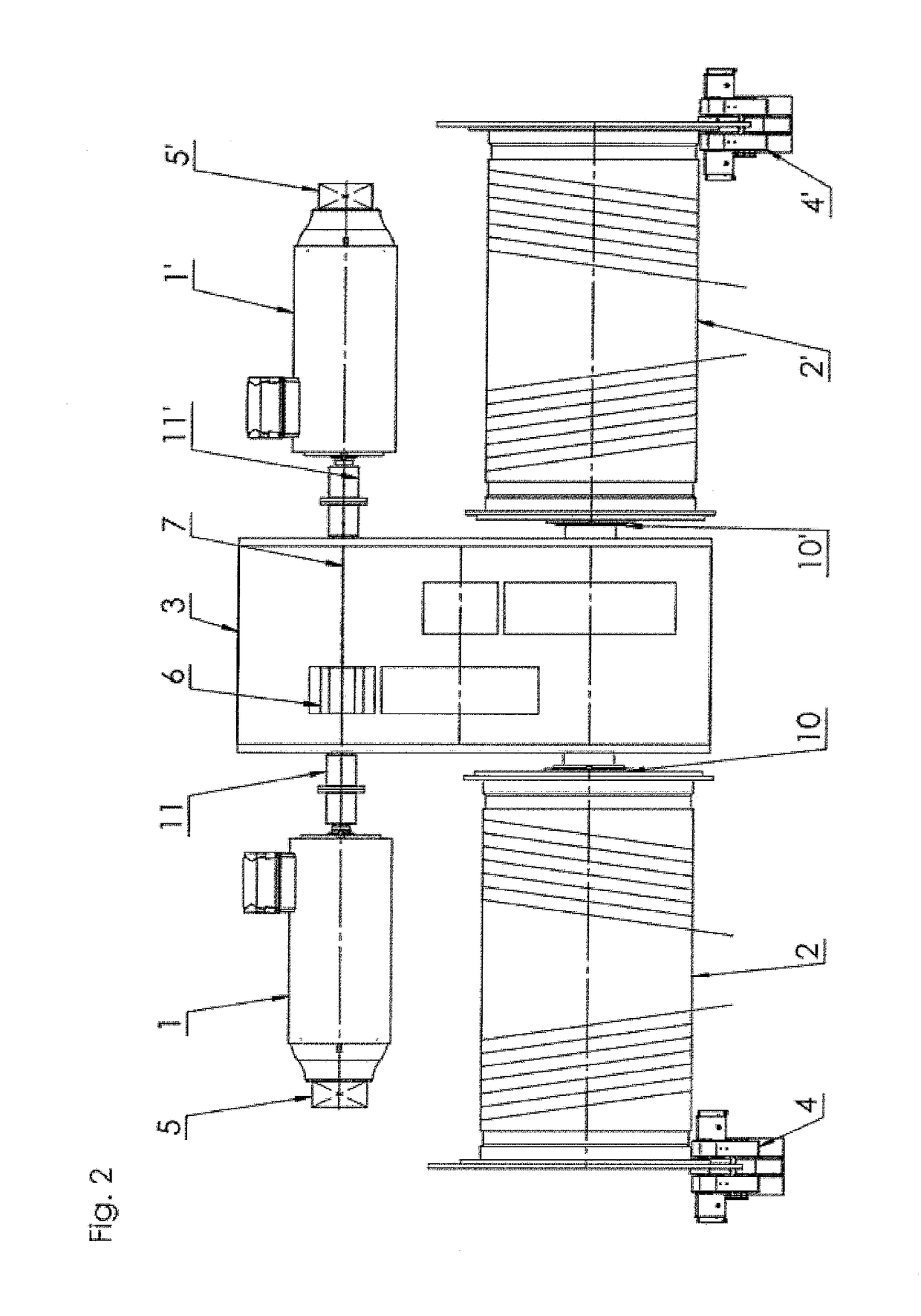
[0031]Referring to the drawing the drive train according to the invention which is intended in particular for crane lifting mechanisms comprises two drive motors 1, 1′, two cable drums 2, 2′, a reduction transmission 3 disposed between the drive motors 1, 1′ and the cable drums 2, 2′, an automatic overrun shutdown means and two safety brakes 4, 4′ fitted to the cable drums 2, 2′.

[0032]In addition the drive train according to the invention has active motor locking means 5, 5′ which serve to hold the load in the event of the drive motors 1, 1′ being electrically decelerated to the rotary speed ‘0’ and which can be actively actuated. In that way it is possible to dispense with the per se known passive operating brakes normally arranged between the drive motors 1, 1′ and the reduction transmission 3.

[0033]Provided as the overrun shutdown means is a freewheel 6 which, in each of the embodiments by way of example shown in FIGS. 1 to 4, is integrated in the reduction transmission 3. In the...


PUM


Abstract

A system arrangement for the drive train of lifting mechanisms, such as crane lifting mechanisms, is disclosed. The system arrangement includes at least one drive motor (1, 1′), at least one cable drum (2, 2′) connected thereto, a reduction transmission (3) arranged between the drive motor (1, 1′) and the cable drum (2, 2′), an automatic overrun shutdown freewheel (6), and at least one safety brake (4, 4′). To optimize such a drive train, at least one active motor locking assembly (5, 5′) is utilized to hold the load when the drive motor (1, 1′) is decelerated electrically to a rotary speed of zero. The active motor locking assembly is utilized instead of at least one passive operating brake.

Description

CROSS-REFERENCE TO RELATED APPLICATIONS[0001]This application is a Section 371 of International Application No. PCT / EP2015 / 058287, filed Apr. 16, 2015, which was published in the English language on Jul. 14, 2016 under International Publication No. WO 2016 / 110333 A1 and the disclosure of which is incorporated herein by reference.BACKGROUND OF THE INVENTION[0002]The invention concerns a system arrangement for the drive train of lifting mechanisms, in particular crane lifting mechanisms, comprising at least one drive motor, at least one cable drum connected thereto, a reduction transmission arranged between the drive motor and the cable drum, an automatic overrun shutdown means, and at least one safety brake and a method of operating the system arrangement.[0003]In a known lifting mechanism of the specified kind (EP 1 661 845 B1) there are provided two drive motors which drive two cable drums by way of a reduction transmission. Provided in the drive train, besides operating brakes and...

Claims


Application Information

Patent Timeline
IPC IPC(8): B66D1/58B66D5/12B66D1/14B66D1/12
CPCB66D1/58B66D1/12B66D5/12B66D1/14B66D2700/0166B66D5/06
Inventor LAUTWEIN, CHRISTOFWAGENER, CHRISTOPH
Owner M A T MALMEDIE ANTRIEBSTECHN
Learn More