Rotator arm stop and roller assembly

a technology of rotating arm and roller, which is applied in the direction of sealing/packing, drilling pipes, and wellbore/well accessories, etc., can solve the problems of increasing the complexity and hence vulnerability of components, increasing the mechanical complexity of instruments, and causing leakage and expensive repairs

Active Publication Date: 2018-11-13
JW JOHNSON EQUIP LEASING CO
View PDF9 Cites 8 Cited by
  • Summary
  • Abstract
  • Description
  • Claims
  • Application Information

AI Technical Summary

Benefits of technology

[0009]The above and other objects, effects, features, and advantages of the present invention will become more apparent from the following

Problems solved by technology

Advances in well head instrumentation have improved the efficiency of oil pumping, but also increased the complexity and hence vulnerably of the components.
Instrumentation has also increased the mechanical complexity.
Jamming can damage components as well as cause the failure of the sucker rod rotator, leading to leaks and expensive repairs as well as non-productive down time for the well.
However, this configuration can become problematic if the cable is tangled, cut or otherwise disengage from either the upper portion of the rig or the arm 35.
However, such multiple cables can more easily become twisted and entangle with each other in high winds.

Method used


Image

  • Rotator arm stop and roller assembly
  • Rotator arm stop and roller assembly
  • Rotator arm stop and roller assembly

Examples


Embodiment Construction

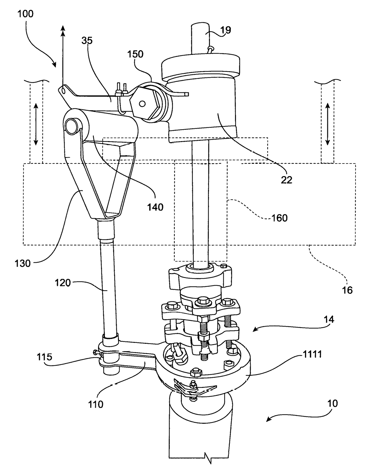
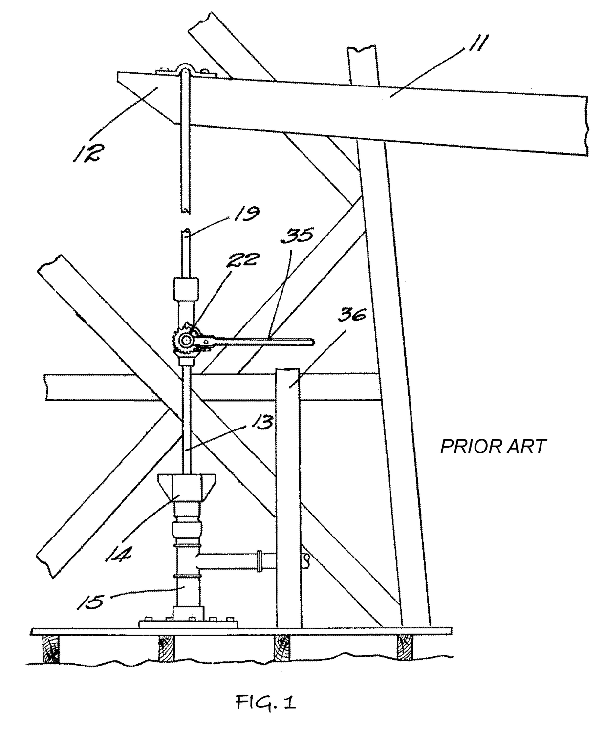
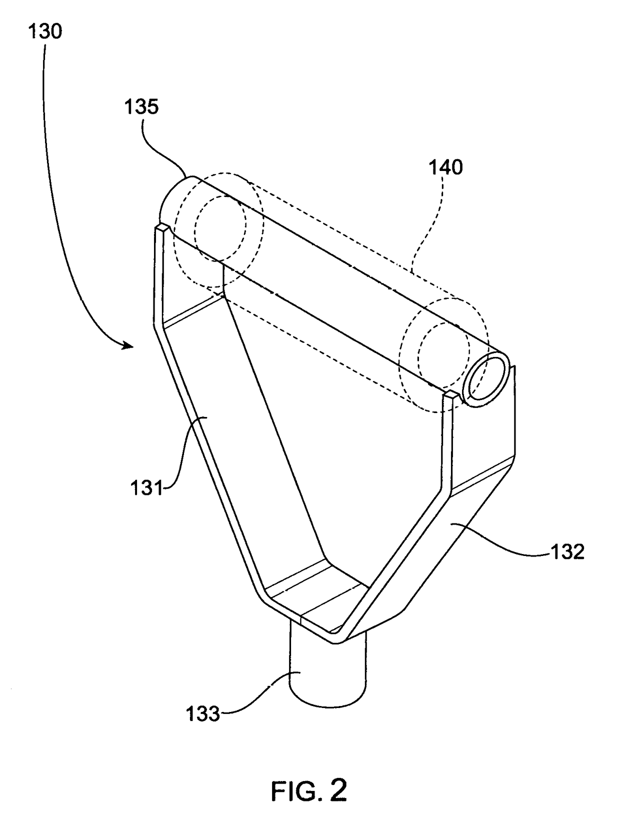
[0030]Referring to FIGS. 1 through 16, wherein like reference numerals refer to like components in the various views, there is illustrated therein a new and improved Rotator Arm Stop and Roller Assembly, generally denominated 100 herein.

[0031]In summary, the preferred and other embodiments of the invention described above improve well operation reliability in all weather reconditions with exposure to oil field chemicals, drilling and petroleum residue by providing a corrosion resistant combination of materials and contacting surfaces.

[0032]In accordance with the present invention the Rotator Arm Stop and Roller Assembly 100 comprises a clamp device 110 having a first cylindrical clamp assembly 111 / 111′, a rigid linear member 118 is connected at a proximal end to the cylindrical clamp assembly. The rigid linear member 118 is in turn connected at the opposing or distal end to a second cylindrical clamp means, such as tube 115. An upright post 120 is attached to the second cylindrical ...


PUM


Abstract

A petroleum extraction pump deploying a sucker rod has an actuator for rotating the portion of the rod in the stuffing box on every stroke to minimize local wear. The rotor handle or arm of the actuator is triggered by an upright roller supported by a an upright rigid linear member, such as a post or tube, that is spaced apart from the well bore by a clamp attached to the main well pipe or stuffing box. The roller rotates with each stroke as it engages the rotator handle. The roller is supported by a Y-shaped saddle to avoid catching on the upstroke of the pumping unit should these member become laterally separated. The device is capable of retrofitting to an existing sucker rod actuator by eliminating a cable to the arm of the actuator and deploying an arm stop member to support the handle in a horizontal orientation until it contacts the roller.

Description

CROSS REFERENCE TO RELATED APPLICATIONS[0001]The present application claims the benefit of priority to the US Provisional Patent application of the same title that was filed on Apr. 17, 2016, having application No. 62 / 148,872, and is incorporated herein by reference.BACKGROUND OF INVENTION[0002]The field of inventions is wellhead equipment and is intended for use in oil wells, where extraction is carried out by using pumping equipment with reciprocating sucker rods.[0003]U.S. Pat. No. 1,623,696 disclosures a sucker rod rotator 22 that deploys a stop post 36 to rotate an actuator handle 35. The sucker rod 19 enters the well head from the top of the stuffing box 14 and extends past the pumping T 15 into the well. Oil pumped from the well is expelled through the pumping T port connected to the horizontal pipe on each upward stroke of the sucker rod 19 by the overhead pivoting beam 11 / 12; the end of the actuator handle will hit the top of the post 36, causing the sucker rod 19 to rotate...

Claims


Application Information

Patent Timeline
Patent Type & Authority Patents(United States)
IPC IPC(8): E21B43/12
CPCE21B43/121E21B43/127E21B33/08E21B17/04
Inventor JOHNSON, WESLEY J
Owner JW JOHNSON EQUIP LEASING CO
Why Eureka
Try Eureka