Electric brake device and electric brake device system

a technology of brake device and brake device, which is applied in the direction of brake system, mechanical equipment, transportation and packaging, etc., can solve the problems of pad wear progressing beyond its limit, affecting the performance and the brake rotor exhaustion, so as to prevent the wear of the brake rotor and increase the cost and space

Active Publication Date: 2018-11-13
NTN CORP
View PDF31 Cites 1 Cited by
  • Summary
  • Abstract
  • Description
  • Claims
  • Application Information

AI Technical Summary

Benefits of technology

[0018]An object of the present invention is to provide an electric brake device and an electric brake device system that can prevent pad wear from progressing beyond its limit, and also can estimate the wear of a friction pad without increase in cost and space.
[0027]Regarding this, since the retraction limit position at which the linear motion portion 14 is most separated from the brake rotor 5 is used as a reference, the reference position of a motor rotation angle can be accurately set irrespective of whether the friction pad 6 is worn. Accordingly, the wear amount of the friction pad 6 can be accurately estimated. This enables the progression of wear of the friction pad 6 to be detected at all times, thereby preventing the wear of the friction pad 6 from progressing beyond its wear limit. By predicting, to a certain degree, the timing at which the friction pad 6 reaches its wear limit, a maintenance work for the electric brake device can be performed at an appropriate time before the timing at which the wear limit is reached.
[0028]A dedicated sensor for detecting the wear amount of the friction pad 6 is not required, and the motor rotation angle detector 28 which is basically required for electric brake devices is used to detect respective motor rotation angles at the retraction end and the advance end of the linear motion portion 14. This enables the wear of the friction pad 6 to be estimated without involving as great increase in cost and space as the method (4) in which the pad wear amount is estimated from relative positions of the slide pins and the caliper.
[0034]The braking force estimation section 30 may include a load sensor 13 configured to detect an axial load of the linear motion mechanism 4. In this case, when the controller 7 causes the linear motion portion 14 to advance from the retraction end, a value detected by the load sensor 13 gradually increases. The value detected by the load sensor 13 becomes maximum at a position where the friction pad 6 comes into contact with the brake rotor 5. By using the load sensor 13 in this way, it is possible to accurately detect the contact position of the friction pad 6.
[0038]In a case where a normal braking operation is performed, when the wear amount of the friction pad 6 is being estimated during travelling of the vehicle and a normal brake operation is performed, the controller 7 operates the electric brake devices A1 in the quadrants that are diagonal to each other. This can suppress occurrence of undesired yaw moment to the vehicle, and can suppress that any behaviors work on the vehicle. The controller 7 may be provided with a warning signal output section 33 configured to output a warning signal to a higher-order control unit of the controller 7 when the wear amount of the friction pad 6 estimated by the pad wear amount estimation section 37 is equal to or greater than a threshold. A driver of the vehicle can recognize that the friction pad 6 almost reaches its wear limit by a warning display, a warning sound, or the like that is outputted from the higher-order control unit. Therefore, at an appropriate time before the timing at which the wear limit is reached, a maintenance work can be performed on the electric brake device having the friction pad 6 that almost reaches the wear limit.

Problems solved by technology

Therefore, the pad wear may progress beyond its limit in a situation where a maintenance work cannot be performed immediately.
In addition, with such a method in which the pad is brought into direct contact with a brake rotor, the exhaustion of the brake rotor may be promoted at the time when the pad wear limit is reached because the pad wear is found only after the pad wear limit is reached.
With the method (4) in which the pad wear amount is estimated from relative positions of slide pins and a caliper, a dedicated sensor is required, which may lead to increase in cost, and the area surrounding a brake cylinder, including the slide pin portion, is subjected to severe thermal and vibration conditions.
Therefore, in the case where a sensor or the like is mounted, it is difficult to achieve desired durability and reliability, and the cost and the space may be further increased from the viewpoint of protecting the sensor.

Method used


Image

  • Electric brake device and electric brake device system
  • Electric brake device and electric brake device system
  • Electric brake device and electric brake device system

Examples


Embodiment Construction

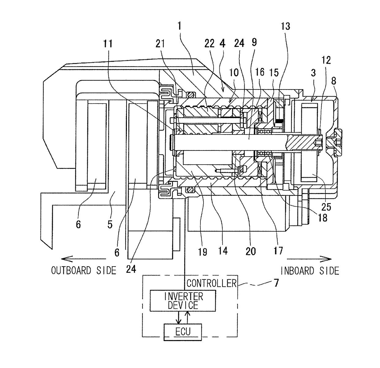
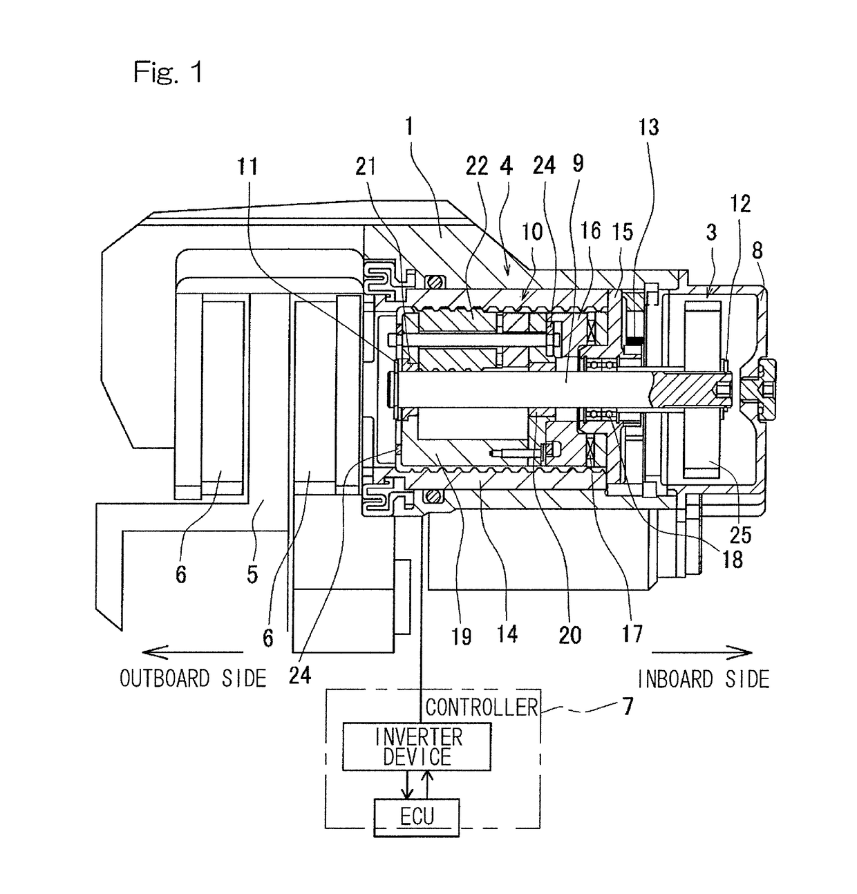
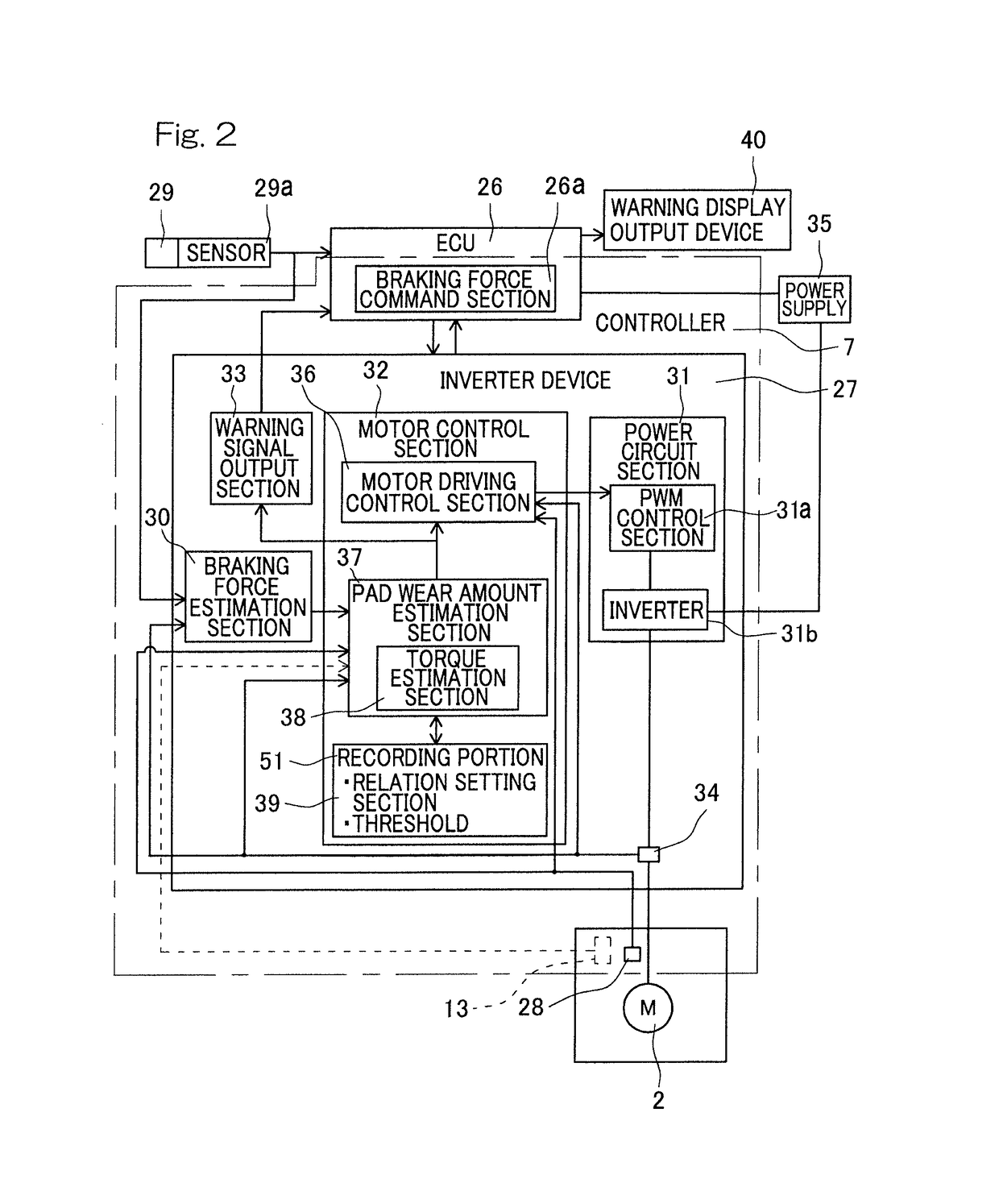
[0049]An electric brake device according to an embodiment of the present invention will be described with reference to FIGS. 1 to 5B. As shown in FIG. 1, the electric brake device includes a housing 1, an electric motor 2 (FIG. 2), a speed reduction mechanism 3 that reduces the speed of rotation of the electric motor, a linear motion mechanism 4, a brake rotor 5, a friction pad 6, a locking mechanism (not shown), and a controller 7 that controls the electric motor. The electric motor 2 is supported by the housing 1. The linear motion mechanism 4 is incorporated into the housing 1 so as to apply a braking force to the brake rotor 5 (a disc rotor in this example) by an output from the electric motor 2. The housing 1 has an opening end covered by a cover 8.

[0050]The linear motion mechanism 4 will now be described. The linear motion mechanism 4 is a mechanism that converts a rotary motion outputted from the speed reduction mechanism 3 into a linear motion and brings the friction pad 6 i...


PUM


Abstract

The electric brake device includes an electric motor, a friction pad, a linear motion mechanism, a braking force command section, a braking force estimation section, and a controller. The controller is provided with a pad wear amount estimation section to estimate a wear amount of the friction pad and a motor rotation angle detector to detect a motor rotation angle. The pad wear amount estimation section estimates a wear amount of the friction pad from the rotation angle of the electric motor, obtained by the motor rotation angle detector, which rotation angle corresponds to a distance between a retraction end at which a linear motion portion of the linear motion mechanism is separated from a brake rotor and an advance end at which the linear motion portion approaching the brake rotor generates the braking force.

Description

CROSS REFERENCE TO THE RELATED APPLICATION[0001]This application is a continuation application, under 35 U.S.C. § 111(a), of international application No. PCT / JP2015 / 057770, filed Mar. 16, 2015, which is based on and claims Convention priority to Japanese patent application No. 2014-059503, filed Mar. 24, 2014, the entire disclosure of which is herein incorporated by reference as a part of this application.BACKGROUND OF THE INVENTION[0002]Field of the Invention[0003]The present invention relates to an electric brake device and an electric brake device system that can detect the progression of wear of a friction pad at all times to prevent the friction pad from reaching its wear limit, thereby allowing a maintenance work or the like to be performed at an appropriate time.[0004]Description of Related Art[0005]As conventional methods for controlling an electric brake, the following techniques have been proposed.[0006](1) An electric brake device using a motor and a linear motion mechan...

Claims


Application Information

Patent Timeline
Patent Type & Authority Patents(United States)
IPC IPC(8): B60T8/00F16D66/02F16D65/18B60T13/74F16D55/226F16D121/24F16D125/40
CPCF16D65/18B60T13/741F16D66/021F16D55/226F16D2125/40F16D2121/24
Inventor MASUDA, YUI
Owner NTN CORP
Why Eureka
Try Eureka