Electron microscope electron gun for facilitating position adjustment and electron microscope including same

a technology of electron gun and electron microscope, which is applied in the direction of basic electric elements, electric discharge tubes, electrical apparatus, etc., can solve the problems of reducing the number of electrons reaching a sample, affecting the quality of electron microscopes, so as to facilitate assembling and disassembling operation, facilitate the adjustment, and simplify the structure

Active Publication Date: 2018-11-13
KOREA RES INST OF STANDARDS & SCI
View PDF10 Cites 0 Cited by
  • Summary
  • Abstract
  • Description
  • Claims
  • Application Information

AI Technical Summary

Benefits of technology

[0022]According to the embodiments of the present invention, the electron gun for facilitating position adjustment can move the plate-shaped top portion on the double O-ring or the magnetic fluid seal without a bellows surrounding and sealing the electron beam generator, in order to align the center axis of an electron beam with an anode plate or field emission electron source facing a Wehnelt cylinder and a secondary anode arranged in parallel to a primary anode. Therefore, the electron beam can be easily adjusted, and the structure can be simplified in comparison to when a bellows is used. Furthermore, the assembling and disassembling operation can be facilitated, and the reusable rubber ring is used. Moreover, soft steel which can maintain an ultra-high vacuum at a similar level to stainless steel and has a large relative permeability is used as the material of the chamber in order to prevent an introduction of a stray magnetic field without an additional structure such as Mu-metal or permalloy surrounding the electron beam generator. Therefore, the electron gun can be manufactured through a simple process, and does not need to employ a complex structure.

Problems solved by technology

When the center axes are misaligned from each other, a problem may occur in electron beam alignment, and the number of electrons reaching a sample may decrease.
In this case, an aberration may occur in an electromagnetic field lens, and the sample examination resolution may be degraded.
Thus, the operation takes a lot of cost, and a metal bellows requires a high manufacturing cost.
In order to perform sealing using a metal gasket, an operator must apply a predetermined force, and may have inconvenience in the disassembling / assembling operation because a number of assembling screws are need.
Thus, the structure of the electron gun becomes complex.
However, the permalloy or Mu-metal is expensive and requires a high processing cost.

Method used


Image

  • Electron microscope electron gun for facilitating position adjustment and electron microscope including same
  • Electron microscope electron gun for facilitating position adjustment and electron microscope including same
  • Electron microscope electron gun for facilitating position adjustment and electron microscope including same

Examples


Embodiment Construction

[0026]Hereinafter, preferred embodiments of the present invention will be described in detail with reference to the accompanying drawings such that the present invention can easily be embodied by a person with ordinary skill in the art to which the invention pertains. Before the present invention is described in detail, the terms or words used in this specification and claims should not be limited to typical definitions or dictionary definitions. Therefore, the configurations described in this specification and the drawings are only preferred embodiments of the present invention, and do not fully represent the technical idea of the present invention. Thus, various equivalents and modifications capable of replacing the embodiments may be provided at the point of time that the present application is filed.

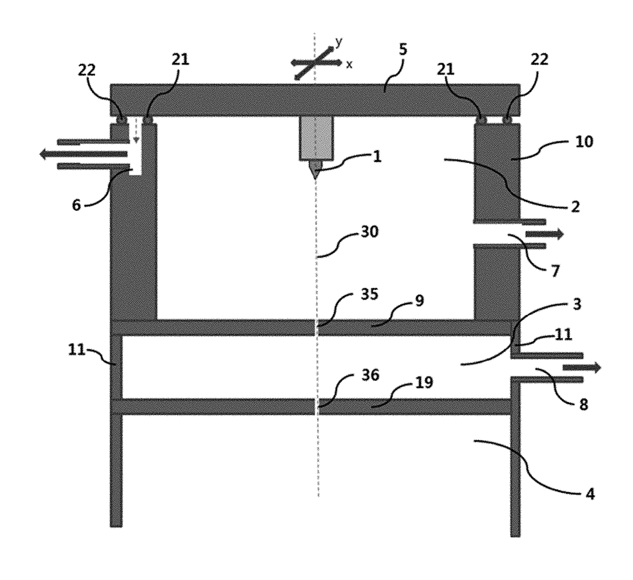
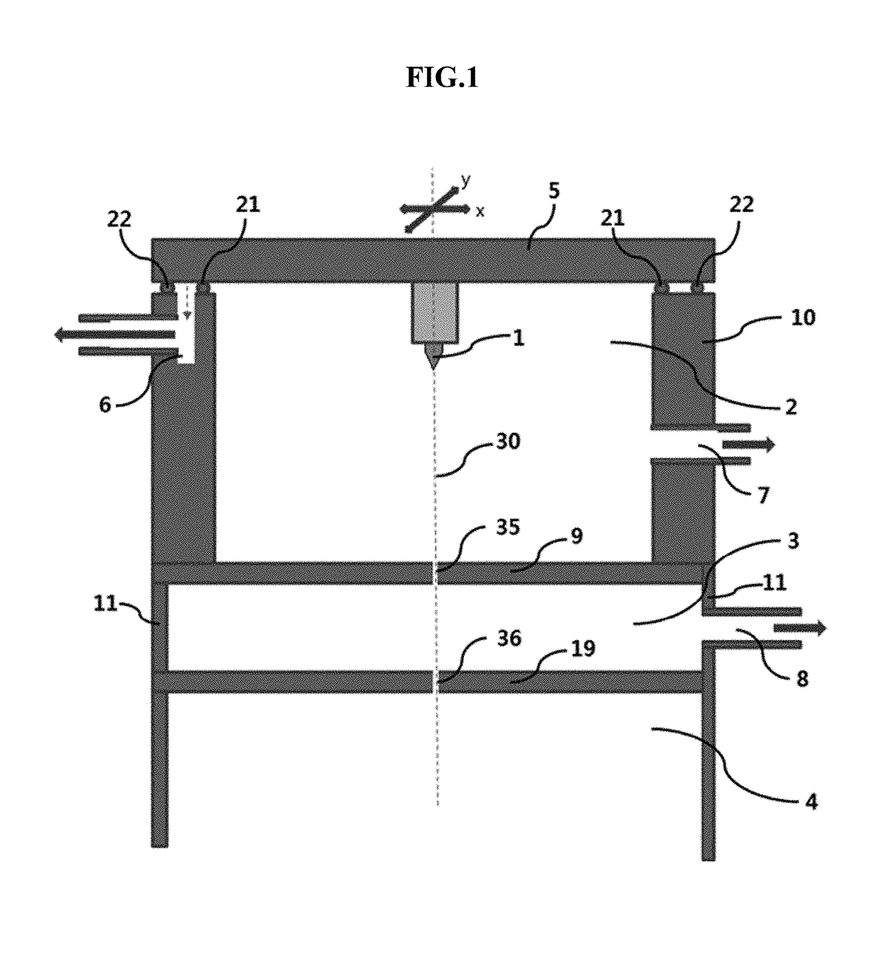
[0027]FIG. 1 is a conceptual view illustrating an electron gun for maintaining a vacuum with a double O-ring between the top edge surface of a tube-shaped side portion and a plate-sh...


PUM


Abstract

The present invention relates to an electron gun for facilitating position adjustment, and an electron microscope including the same, the electron gun improving a vacuum structure so as to easily move a filament block or an electron tip of an electron gun without having bellows for maintaining a vacuum when the center axis of the filament block or the electron tip of the electron gun is mechanically misaligned with the center axis of a anode and a focusing lens.

Description

TECHNICAL FIELD[0001]The present invention relates to an electron microscope and an electron gun, and more particularly, to an electron gun for facilitating position adjustment, which includes an enhanced vacuum structure capable of moving a filament block or electron tip of the electron gun without a metallic bellows for maintaining a vacuum, when the center axis of the filament block or the electron tip of the electron gun is mechanically misaligned from the center axes of an anode and a focusing lens, and thus facilitates an assembling or disassembling operation, and an electron microscope including the same.BACKGROUND ART[0002]The scanning electron microscope (SEM) scans a sample with an electron beam in a two-dimensional manner, detects a secondary electron emitted from the sample, and creates an image using the detected electron. The SEM has a similar configuration to an optical microscope that includes an object lens and creates an image using light reflected from the surface...

Claims


Application Information

Patent Timeline
Patent Type & Authority Patents(United States)
IPC IPC(8): H01J37/06H01J37/065H01J37/26
CPCH01J37/065H01J37/06H01J37/26H01J2237/06341H01J2237/061H01J37/07H01J2237/024H01J2237/06325H01J2237/26
Inventor CHO, BOK LAEPARK, IN YOUNG
Owner KOREA RES INST OF STANDARDS & SCI
Why Eureka
Try Eureka