

Movable connector
a technology of movable connectors and connectors, applied in the direction of coupling contact members, coupling device connections, electrical devices, etc., can solve the problem of inability to easily increase the spring length, and achieve the effect of increasing the reliability of conductive connections, reducing the size of movable connectors, and increasing spring lengths
- Summary
- Abstract
- Description
- Claims
- Application Information
AI Technical Summary
Benefits of technology
Problems solved by technology
Method used
Image

Examples
first embodiment (
FIGS. 1 to 10)
Structure of Movable Connector 1
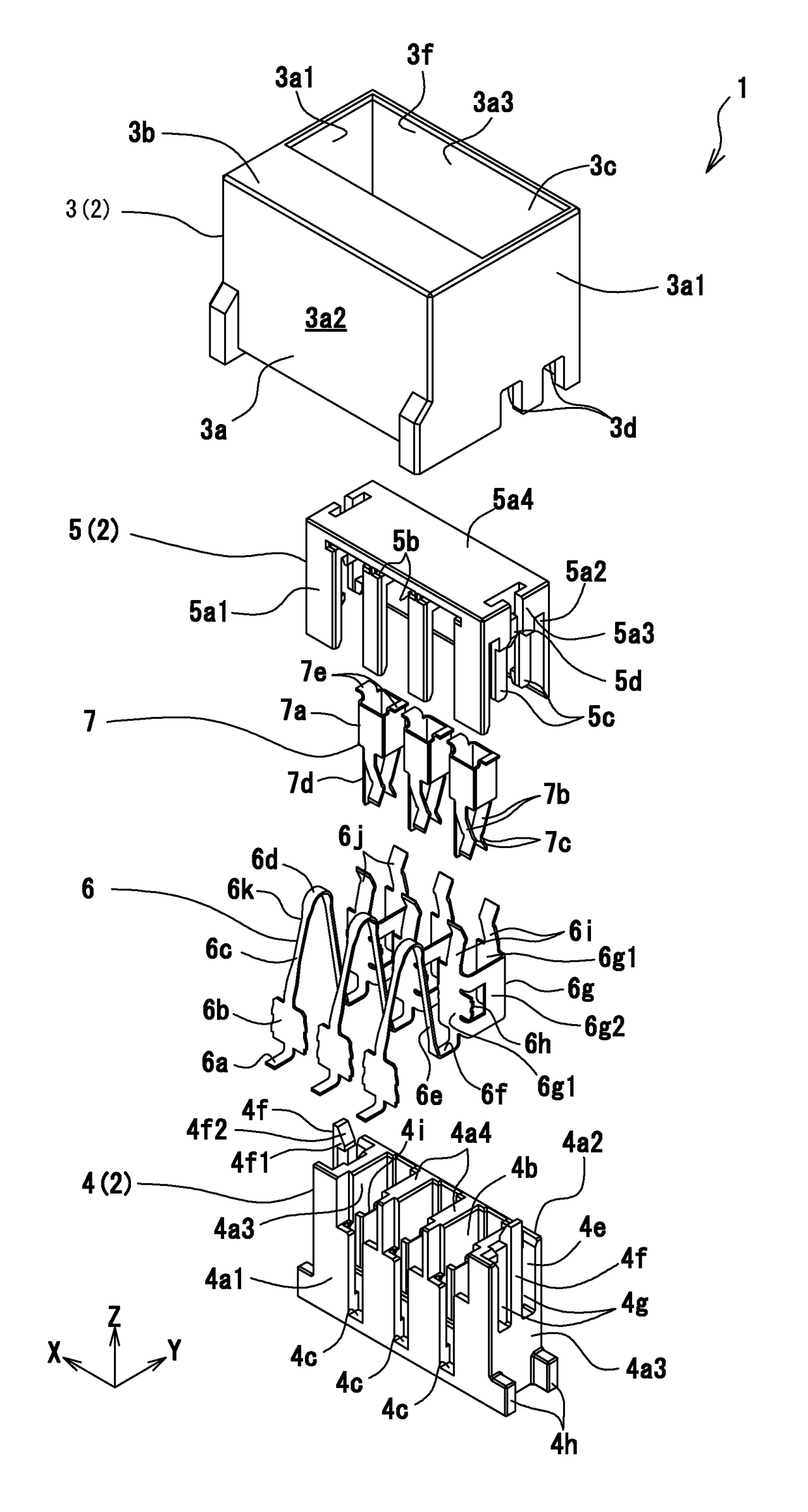
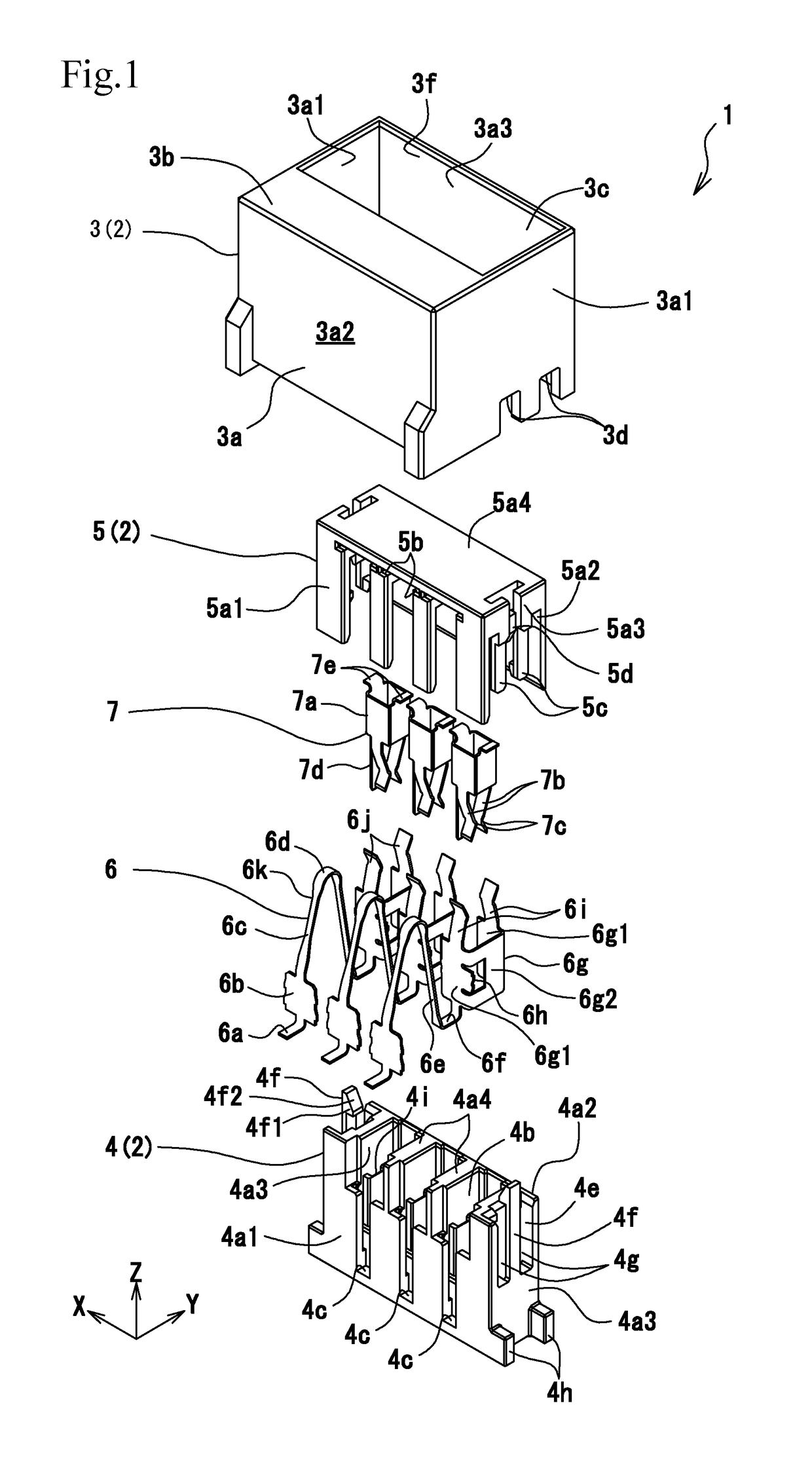
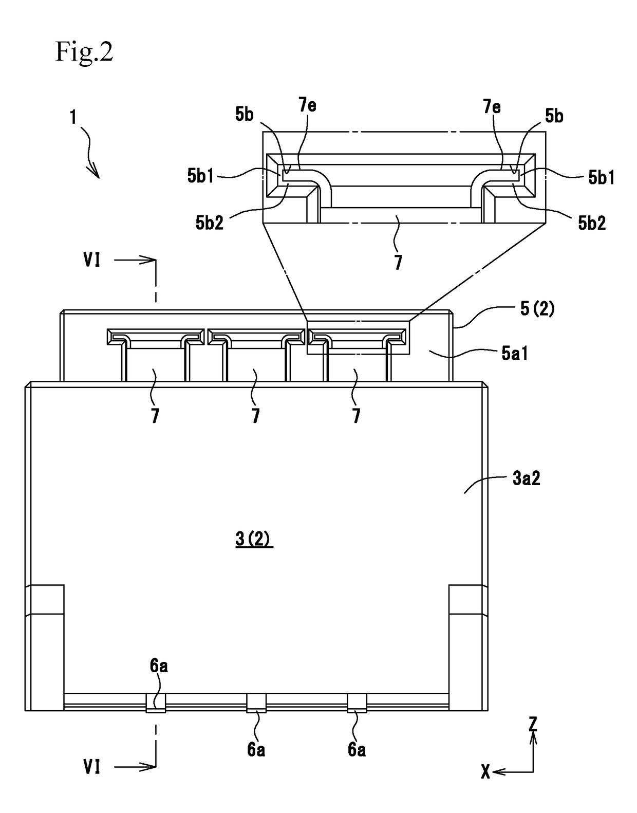
[0040]The movable connector 1 includes a housing 2, which is a molded body made of a rigid resin. The housing 2 includes a fixed housing 3, a movable housing 4, and an operation housing 5. Reference numeral 6 denotes substrate connection terminals formed of metal pieces, and 7 denotes relay terminals formed of metal pieces. The substrate connection terminals 6 are fixed to the fixed housing 3 and the movable housing 4. The relay terminals 7 are held by the operation housing 5. Fixed Housing 3
[0041]The fixed housing 3 is mounted on a substrate P (FIG. 9). The fixed housing 3 is box-shaped, and includes a tubular wall 3a and a top portion 3b that covers a front section in the Y direction at the top end of the tubular wall 3a. The fixed housing 3 defines an interior space 3c therein.
[0042]The tubular wall 3a includes left and right side walls 3a1 having engagement recesses 3d at the bottom ends thereof. The engagement recesses 3d engage wit...
second embodiment (
FIGS. 11 to 14)
[0078]The second embodiment differs from the first embodiment in that each substrate connection terminal 6 does not include the pair of elastic arms 6i and the pair of contact portions 6j. The second embodiment also differs from the first embodiment in that each relay terminal 7 includes acutely bent portions 7f, which serve as “spring portions”, and a pair of terminal connection contact portions 7g, which serve as “second contact portions”. The acutely bent portions 7f extend from the pair of contact portions 7c, and are bent. The terminal connection contact portions 7g extend from the acutely bent portions 7f and come into conductive contact with the base portion 6g (plate pieces 6g1) of the corresponding substrate connection terminal 6. Other structures, operation, and effects of the second embodiment are the same as those of the first embodiment. Therefore, only the differences will be described.
[0079]In the first embodiment, the elastic arms 6i and the contact po...
PUM
 Abstract
Description
Claims
Application Information