Base unit for a vehicle

a technology for vehicles and base units, applied in the direction of resilient suspensions, transportation and packaging, lifting devices, etc., to achieve the effect of ensuring the stability of the platform

Active Publication Date: 2018-11-20
NIFTYELEVATOR
View PDF35 Cites 1 Cited by
  • Summary
  • Abstract
  • Description
  • Claims
  • Application Information

AI Technical Summary

Benefits of technology

[0012]Because the suspension element cannot move upwards from its upper position in engagement with the stop member, the platform cannot tilt significantly, this being essential for stability. The suspension element is normally maintained in this position by the biasing mechanism, even if one of the wheels is suspended above the ground, to ensure that the stability is not compromised. However, by activating the actuator the suspension element can be allowed to drop down to the lower position so that it can maintain contact with the ground even when the platform is standing on or travelling over an uneven surface. This improves the confidence of the operator and, if the wheels are driven, allows drive to be provided by all the drive wheels. However, as a large part of the weight of the suspension element and the attached wheel is still carried by the chassis, this weight contributes to the overall weight of the base unit and to the stability of the platform.
[0013]Advantageously, the biasing mechanism includes a resilient biasing element that biases the suspension element towards the upper position, and the actuator is operable to urge the suspension element towards the lower position. This provides a simple and effective mechanism for selecting the operating condition of the suspension mechanism according to the operational circumstances.
[0014]Advantageously, the resilient biasing element applies a biasing moment MB to the suspension element that has a value that is greater than the weight moment MW of the suspension element when the suspension element is in the upper position. In a preferred embodiment, the resilient biasing element applies a biasing moment MB to the suspension element that has a value in the range 1.0 to 1.5, preferably 1.0 to 1.1, times the weight moment MW of the suspension element when the suspension element is in the upper position. Therefore, when the drive system is not being used and the hydraulic actuator is not pressurised, the suspension elements are urged upwards and are held in their housings. Because the force exerted by the resilient biasing element is more than the force needed to lift the wheel, the full mass of the wheel assembly contributes to the overall weight of the base unit. The stability of the platform is not therefore compromised.
[0015]For example, the suspension element and wheel of a large MEWP may typically weigh approximately 200 kg and the resilient biasing member (for example a spring) may be arranged to exert a moment on the suspension element that is sufficient to support a weight of approximately 210 kg (allowing also for the additional moment needed to overcome pin frictions and to compensate for hysteresis in the biasing member). Therefore, when the platform is standing on uneven ground and one of the wheels is suspended above the ground, its full weight contributes to the stability of the MEWP.
[0020]Advantageously, the base unit includes a pair of opposed suspension elements arranged to pivot about substantially horizontal pivot axes, and a common biasing mechanism that interconnects the two opposed suspension elements. This simplifies the mechanism and reduces the number of parts and the weight of the mechanism. In particular, as three points are required to define a plane, three of the wheels will always be in contact with the ground. The fourth wheel will drop into contact with the ground but will only press lightly on the ground. Therefore the machine only needs suspension on two opposed wheels (that is, on one axle) and the suspension for only one wheel of an axle is required to operate at any one time. This allows much of the spring / actuator mechanism to be shared between the two opposed wheels, thereby greatly reducing the cost and complexity of the system. Alternatively, each suspension element may include a separate biasing mechanism.
[0025]Advantageously, the control system is configured to prevent actuation of the actuator when the lifting mechanism is in a lifted condition, so that when the lifting mechanism is in a lifted condition each suspension element is located in the upper position. Therefore, when the lifting mechanism is activated, pressure will be released from the actuator and each suspension element will either remain in or return slowly to the upper position. This ensures that the base unit has maximum stability when the lifting mechanism is activated. Further, in the event of a failure of the control system or the hydraulic system, the actuator is preferably deactivated so that the spring returns the wheel to a safe, stable position.

Problems solved by technology

However, as a large part of the weight of the suspension element and the attached wheel is still carried by the chassis, this weight contributes to the overall weight of the base unit and to the stability of the platform.

Method used


Image

  • Base unit for a vehicle
  • Base unit for a vehicle
  • Base unit for a vehicle

Examples


Embodiment Construction

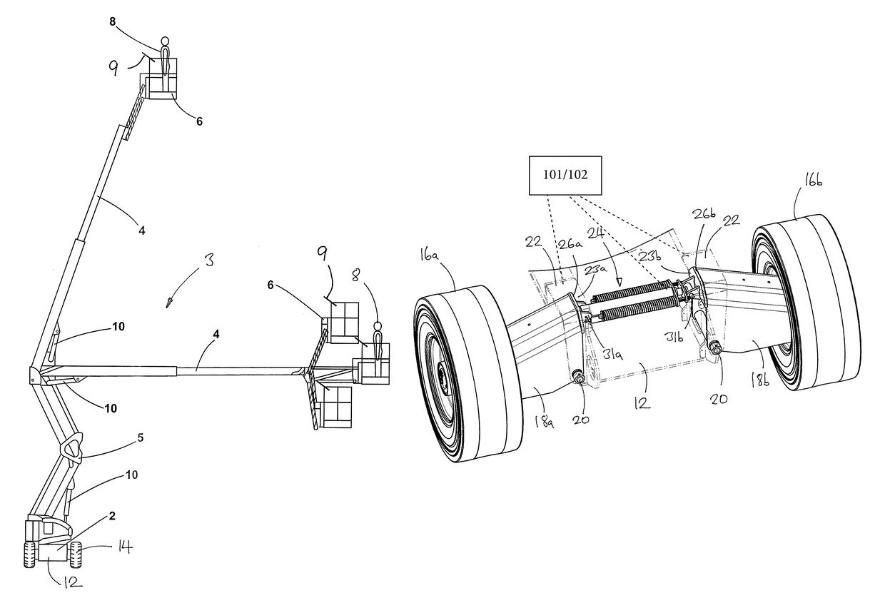
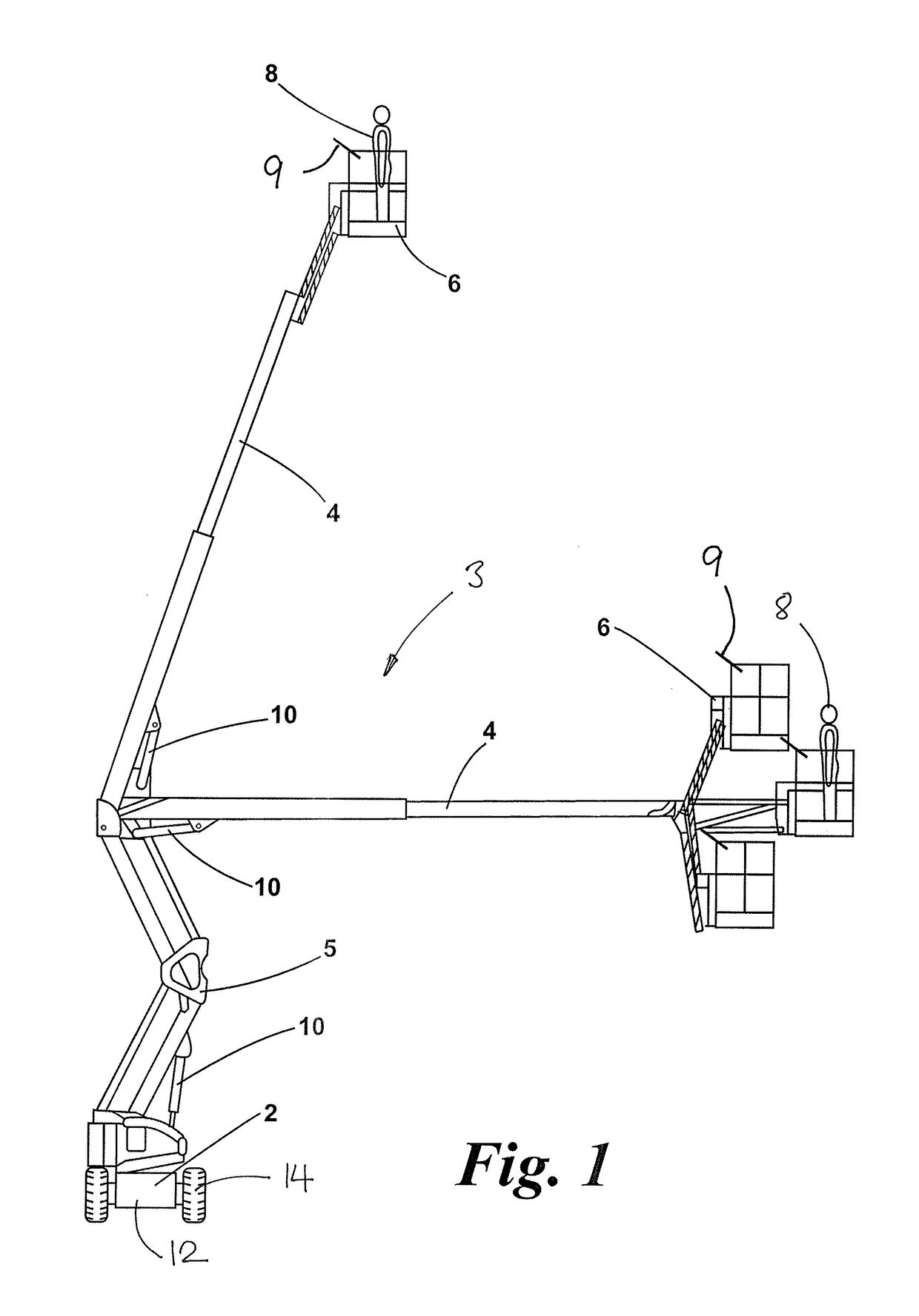
[0035]FIG. 1 shows a typical mobile elevating work platform, which includes a wheeled base 2, a hydraulically operated lifting mechanism 3 comprising an extending boom 4 and a rising structure 5, and a cage 6 for a human operator 8, including a control console 9 for controlling operation of the MEWP. The boom 4, which is shown here in two different operating positions, may be retracted and folded onto the wheeled base 2 for transportation or storage. Movement of the boom is controlled by various hydraulic cylinders 10, which are connected to a hydraulic drive system (not shown) that is controlled via the control console 9.

[0036]The components of the MEWP as described above are all conventional and will not therefore be described in further detail. It should be understood that the mobile elevating work platform may take various alternative forms.

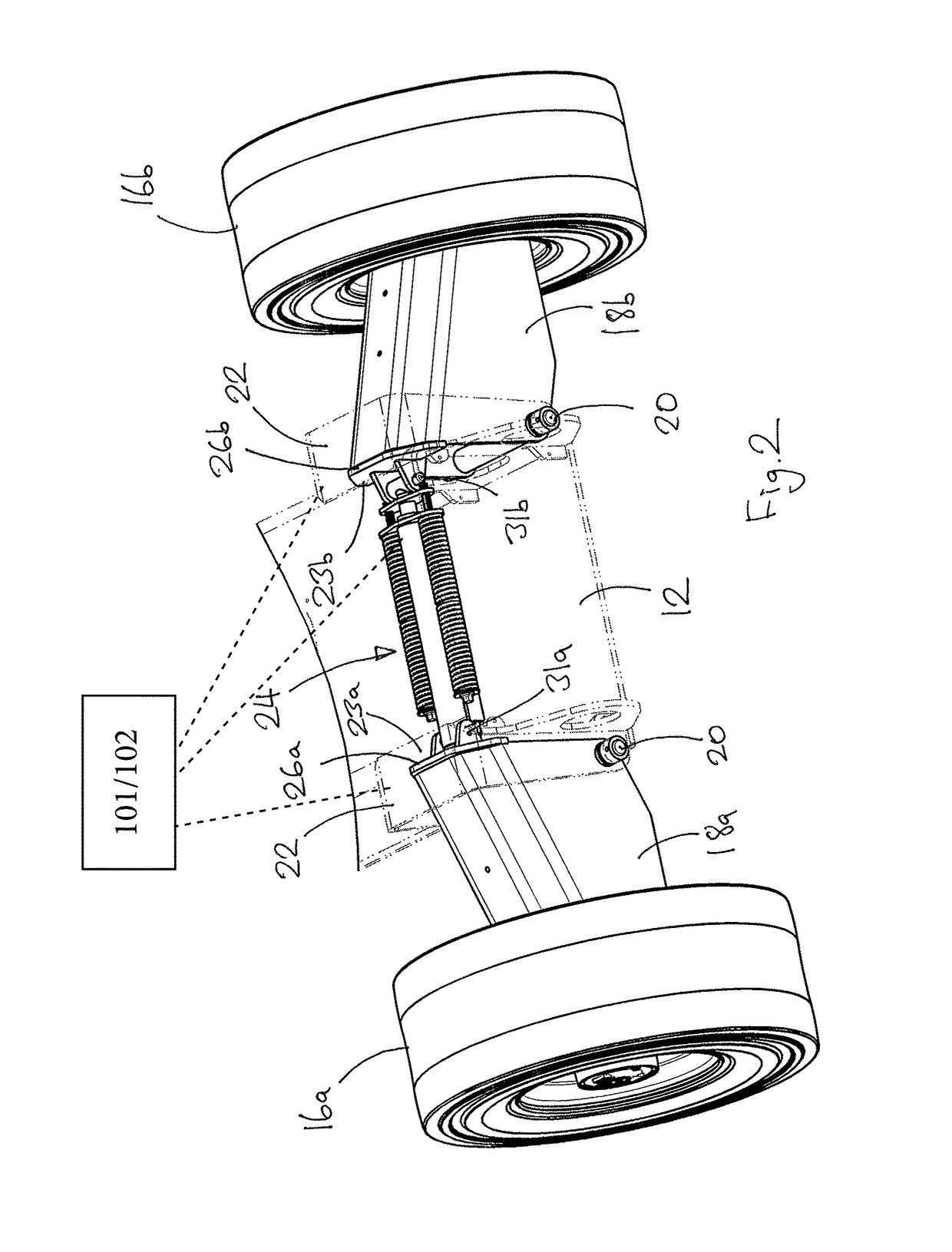
[0037]In this example the base unit 2 includes a chassis 12, a pair of steerable wheels 14 that are mounted in conventional manner on a fixe...


PUM


Abstract

A base unit for a vehicle such as a mobile work platform includes a chassis and multiple wheels, at least one of the wheels being mounted on the chassis by a suspension mechanism including a suspension element. The suspension element pivots relative to the chassis about a substantially horizontal pivot axis between an upper position and a lower position, and a stop member engages the suspension element in the upper position to limit its upwards movement. A biasing mechanism exerts a biasing force on the suspension element to urge the suspension element upwards towards the upper position. The biasing mechanism includes an actuator which adjusts the biasing force so that, in a first operating condition, the biasing force is greater than the force needed to maintain the suspension element in engagement with the stop member when the wheel is suspended, and in a second operating condition the biasing force is less than the force needed to maintain the suspension element in engagement with the stop member when the wheel is suspended.

Description

RELATED APPLICATIONS[0001]The instant application is the U.S. National Phase under 35 U.S.C. § 371 of International Application No. PCT / GB2013 / 052621 entitled BASE UNIT FOR A VEHICLE, filed Oct. 9, 2013, designating the U.S, which claims priority under 35 U.S.C. § 119(a)-(d) to Great Britain Patent Application No. 1218502.1, filed Oct. 15, 2012, the content of which is herein incorporated by reference in its entirety.Field of the Invention[0002]The present invention relates to a base unit for a vehicle, for example for a mobile elevating work platform (MEWP). The base unit may also be used with other vehicles such as forklifts or telescopic handling machines (“telehandlers”). The invention also relates to a vehicle having such a base unit.BACKGROUND OF THE INVENTION[0003]Mobile elevating work platforms generally have a cage for an operator that is mounted on the end of a hydraulically-operated boom. The boom is mounted on a base unit and can be moved up and down or from side-to-side...

Claims


Application Information

Patent Timeline
Patent Type & Authority Patents(United States)
IPC IPC(8): B66F11/04B60K7/00B60G17/02B60G17/005B60G3/08
CPCB66F11/04B66F11/046B60K7/00B60G17/021B60G3/08B60G17/005B60G2300/06B60G2204/46B62D61/12B66F11/044
Inventor BOWDEN, ROGER
Owner NIFTYELEVATOR
Why Eureka
Try Eureka