Flexible plate die-cutting gilding press with high-precision adjusting structure

A die-cutting hot stamping machine, a technology for adjusting structure, applied in the direction of object supply, pile separation, thin material processing, etc., can solve the problem that the die-cutting hot stamping machine does not have flexible adjustment, adjustment of feeding and feeding distance, die-cutting hot stamping Solve problems such as singleness of machine to achieve the effect of improving convenience, ensuring continuity and improving practicability

Inactive Publication Date: 2022-02-25
南通普林派克机电科技有限公司
View PDF0 Cites 0 Cited by
  • Summary
  • Abstract
  • Description
  • Claims
  • Application Information

AI Technical Summary

Problems solved by technology

[0002] For example, the Chinese patent discloses: a flexographic die-cutting hot stamping machine with a high-precision adjustment structure, a stable die-cutting hot stamping machine, publication number: 202020994414.1, because the limit plate constitutes a sliding structure through the slider, the sliding groove and the baffle, so that We can slide the limit plate according to the length of the cardboard, so that the cardboard can move forward stably on the conveyor belt, so as to ensure that the position of the cardboard will not shift, so that the cardboard can be stably stamped. However, the solution is There are the following problems in the process of use: although this solution can ensure that the position of the cardboard will not be shifted, so that the cardboard can be stably stamped, but there is a flexo die-cut stamping machine with a high-precision adjustment structure. During the use of the flexo die-cutting hot stamping machine with a high-precision adjustment structure, for a flexo die-cutting hot stamping machine with a high-precision adjustment structure, the height of the material does not change, and the diameter will change as a cylindrical processed product. When die-cutting and hot stamping, most of the existing ones cannot effectively adjust the conveying distance of feeding and feeding, which leads to the fact that the die-cutting hot stamping machine can only die-cut hot stamping on cylindrical products with a single diameter, which leads to the die-cutting hot stamping machine There is no flexible adjustment effect during use, which also causes problems such as the singleness of the die-cutting hot stamping machine.

Method used


Image

  • Flexible plate die-cutting gilding press with high-precision adjusting structure
  • Flexible plate die-cutting gilding press with high-precision adjusting structure
  • Flexible plate die-cutting gilding press with high-precision adjusting structure

Examples


Embodiment 1

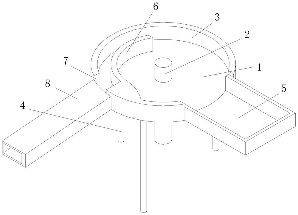
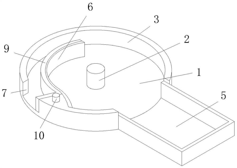
[0034] Example 1: See Figure 1-2, a flexographic die-cutting bronzing machine with a high-precision adjustment structure, including a feeding tray 1, a rotating shaft 2 is fixedly connected to the inside of the feeding tray 1, and a protective shell 3 is connected to the upper side of the feeding tray 1 for rotation, and the protective shell 3 is connected to the upper side of the feeding tray 1. The lower side of the shell 3 is fixedly connected with the support rod 4, the rear side of the protective shell 3 is fixedly connected with the placement plate 5, and the inside of the feeding tray 1 is fixedly connected with the limited-distance outer plate 6, and the lower side of the limited-distance outer plate 6 is connected with the feeding The upper side of the disc 1 is slidingly connected, the left side of the protective shell 3 is provided with a feeding port 7, the left side of the feeding disc 1 is fixedly connected with a feeding plate 8, and the left side of the distanc...

Embodiment 2

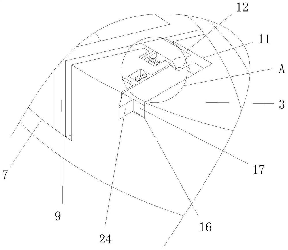
[0036] Example 2: see Figure 3-8 , on the basis of Embodiment 1, the adjustment device includes a moving plate-12, the surface of the moving plate-12 is slidingly connected to the inside of the auxiliary groove-11, and the left side of the moving plate-12 is fixedly connected to the limit plate-13, and the limit The surface of plate one 13 is slidingly connected to the inside of auxiliary groove one 11, the front side of moving plate one 12 is fixedly connected to the rear side of distance limiting inner plate 9, and the rear side of limit plate one 13 is fixedly connected with distance adjustment spring one 14 , the rear end of the distance adjustment spring one 14 is fixedly connected to the inside of the auxiliary groove one 11, the upper side of the moving plate one 12 is provided with a docking groove 15, the shape of the docking groove 15 is a quarter cone shape, and the inside of the protective shell 3 There is an auxiliary groove 16 connected with the auxiliary groove...

Embodiment 3

[0039] Example 3: See Figure 5-7 , the distance adjusting device includes a distance adjusting plate 20, the surface of the distance adjusting plate 20 is slidably connected to the inside of the feeding plate 8, the rear side of the distance adjusting plate 20 is fixedly connected with a slide bar 21, and the rear end of the slide bar 21 is slidably connected to the upper Inside the material plate 8, the surface of the slide bar 21 is slidingly sleeved with a back-moving spring 22, and the front and rear ends of the back-moving spring 22 are respectively fixedly connected to the rear side of the distance-adjusting plate 20 and the inside of the feeding plate 8. The interior is fixedly connected with a semicircular drag-reducing column 23. While the distance-adjusting column 10 is used to drive the moving plate 12 to adjust the distance-limiting inner plate 9, the distance-adjusting column 10 will push the moving plate 2 17 to drive the distance-adjusting block 24 in the auxili...


PUM


Abstract

The invention relates to the technical field of die-cutting gilding machines, in particular to a flexible die-cutting gilding machine with a high-precision adjusting structure, which comprises a feeding disc, a rotating shaft is fixedly connected in the feeding disc, a protective shell is rotatably connected to the upper side of the feeding disc, and a supporting rod is fixedly connected to the lower side of the protective shell. A containing plate is fixedly connected to the rear side of the protective shell, a distance limiting outer plate is fixedly connected into the feeding disc, and the lower side of the distance limiting outer plate is slidably connected with the upper side of the feeding disc. By means of the right triangle shape of a distance adjusting block, it is guaranteed that the distance adjusting block can be attached to the inner side of a feeding plate to slide leftwards, by means of the inclined shape of the distance adjusting block, a distance adjusting plate can be extruded to slide forwards in the feeding plate, and the attaching conveying stability of materials with different diameters is improved; and it is guaranteed that the distance between the protective shell and a distance limiting inner plate and the distance between the feeding plate and the distance adjusting plate can be synchronously adjusted, and the practicability that the feeding disc can convey materials with different radiuses is improved.

Description

technical field [0001] The application relates to the technical field of die-cutting hot stamping machines, in particular to a flexographic die-cutting hot stamping machine with a high-precision adjustment structure. Background technique [0002] For example, the Chinese patent discloses: a flexographic die-cutting hot stamping machine with a high-precision adjustment structure, a stable die-cutting hot stamping machine, publication number: 202020994414.1, because the limit plate constitutes a sliding structure through the slider, the sliding groove and the baffle, so that We can slide the limit plate according to the length of the cardboard, so that the cardboard can move forward stably on the conveyor belt, so as to ensure that the position of the cardboard will not shift, so that the cardboard can be stably stamped. However, the solution is There are the following problems in the process of use: although this solution can ensure that the position of the cardboard will not...

Claims


Application Information

Patent Timeline
Patent Type & Authority Applications(China)
IPC IPC(8): B65H5/18
CPCB65H5/18B65H2701/176
Inventor 张振荣张吉
Owner 南通普林派克机电科技有限公司
Why Eureka
Try Eureka