Control system comprising a control rod

a control system and control rod technology, applied in mechanical equipment, machines/engines, gearing, etc., can solve the problems of high cost of sealing and high risk of degrading

Active Publication Date: 2018-11-20
SAFRAN LANDING SYSTEMS
View PDF9 Cites 1 Cited by
  • Summary
  • Abstract
  • Description
  • Claims
  • Application Information

AI Technical Summary

Benefits of technology

[0006]One object of the invention is to provide a control system in which the sealing around the control rod, between the first zone inside the hydraulic chamber and the second zone outside the hydraulic chamber can be maintained easily.SUMMARY OF THE INVENTION
[0015]3 minimizing the scrapping of high-cost components by positioning the machined friction zones on the removable and low-cost guide piece rather than on the fixed and high-cost hydraulic component.
[0017]This embodiment allows the guide piece to be extracted, from outside the hydraulic chamber, in order for example to carry out seal maintenance. The guide piece can be removed for renovation / treatment in order to improve the peripheral sealing of the control rod.
[0024]By virtue of the invention, the function of dynamic sealing around the mobile control rod is performed reliably and at low cost by transferring it away from the hydraulic component that defines the hydraulic chamber to the guide piece which is inexpensive and easy to replace. Thus, the control system makes it possible, at lower cost, to detect a position of sliding of the hydraulic piston in the high-pressure first zone. According to the position of sliding of the hydraulic piston in the high-pressure first zone, the control rod moves the metal component located in the medium-pressure second zone.

Problems solved by technology

This sealing is expensive to achieve and likely to become degraded over time notably as a result of the wear caused by the repeated movements of the control rod.

Method used


Image

  • Control system comprising a control rod
  • Control system comprising a control rod
  • Control system comprising a control rod

Examples


Embodiment Construction

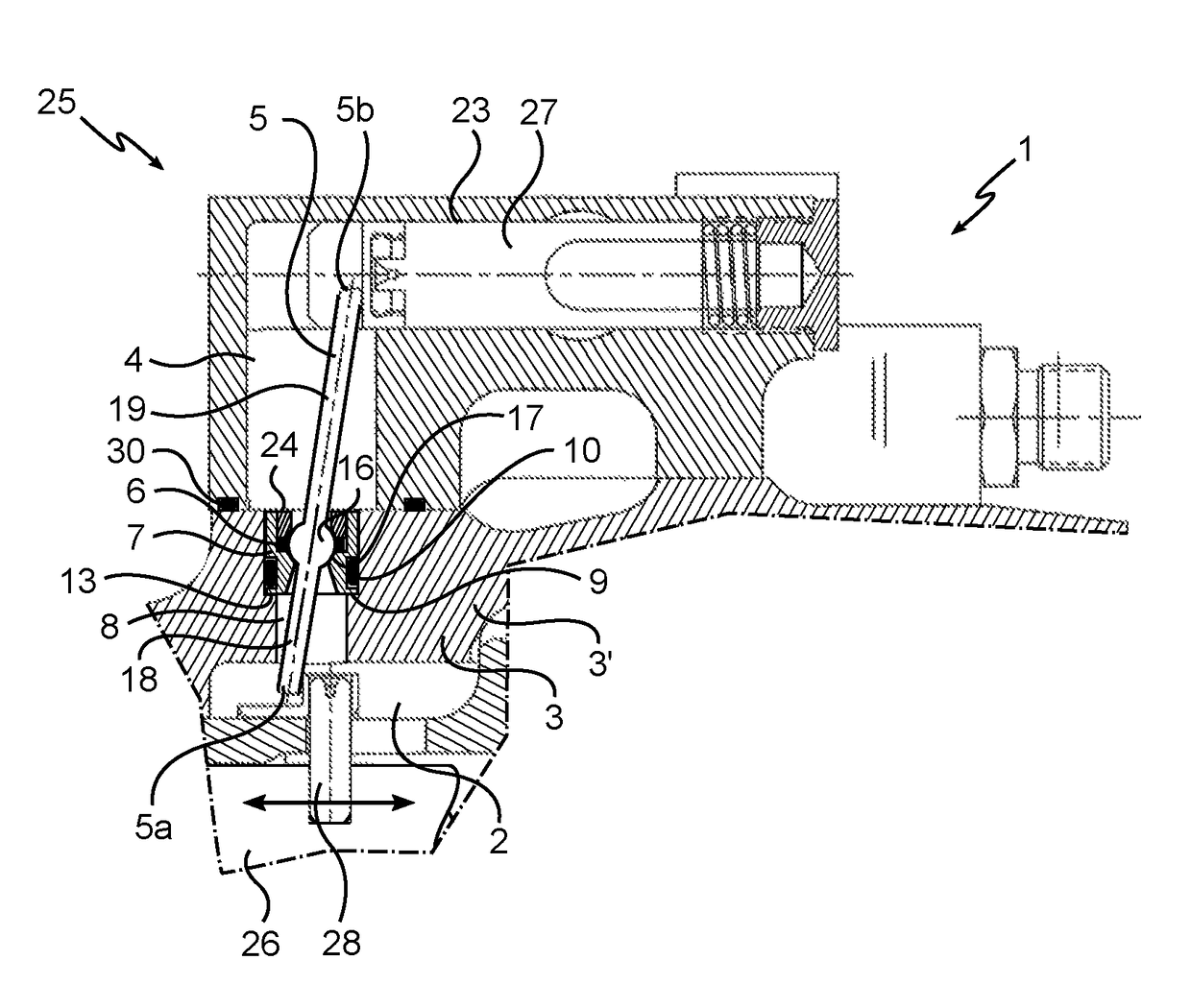
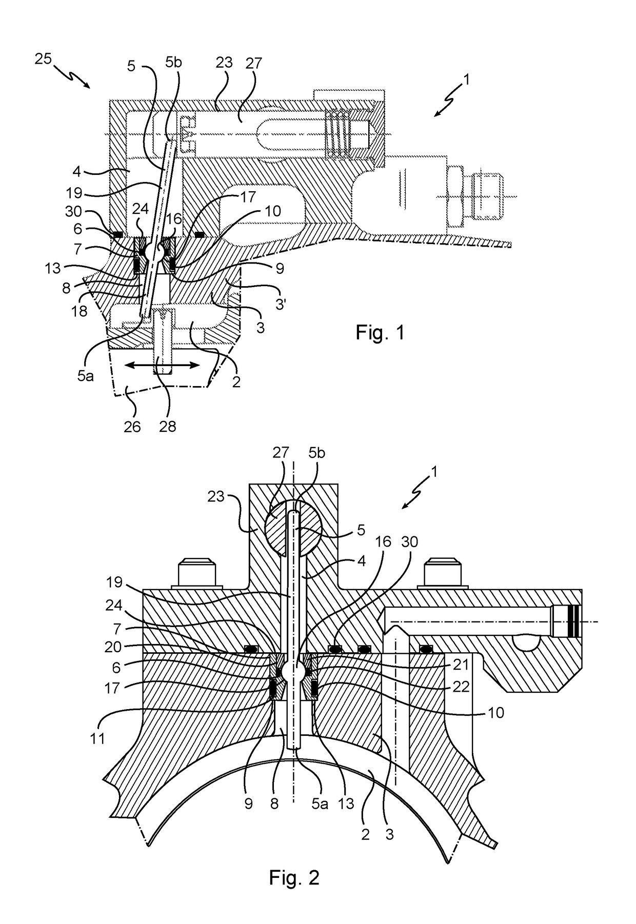
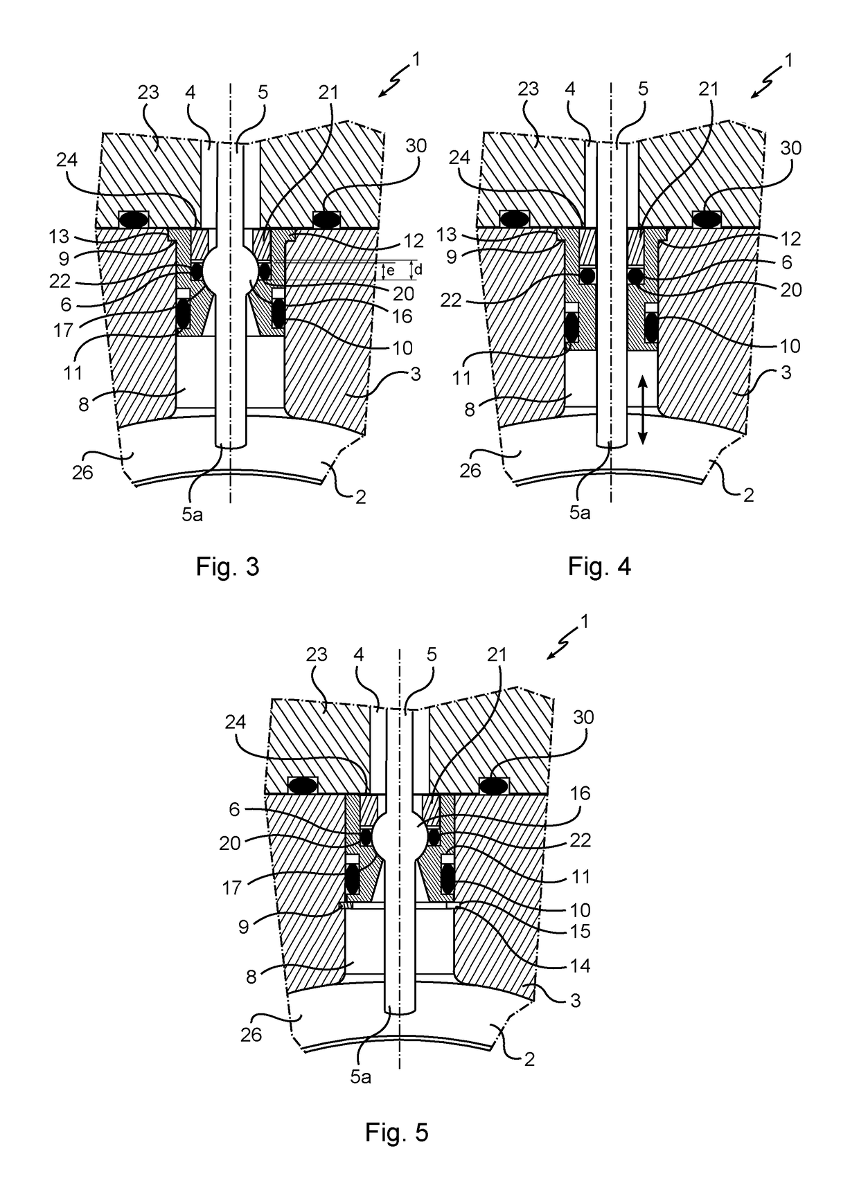
[0031]As indicated previously, the invention relates to a control system 1 comprising a control rod 5 extending between:[0032]a first zone 2 situated in a hydraulic chamber delimited by a chamber wall 3; and[0033]a second zone 4 situated outside the hydraulic chamber.

[0034]A passage 8, in this instance a bore 8, is formed through the chamber wall 3 and extends between the first and second zones 2, 4. A guide piece 7 is positioned inside this passage 8 and is assembled removably with respect to the chamber wall 3. The control rod 5 passes through the passage 8 passing through this guide piece which is hollowed at its centre. A first end 5a of the rod 5 is placed in the first zone 2 and a second end 5b of the rod is placed in the second zone 4. Sealing means 6, in this instance at least one o-ring 22, are arranged around and against the control rod 5 to oppose the passage of fluid, along the rod 5, between the first and second zones 2, 4. These sealing means 6 are assembled inside the...


PUM


Abstract

Control system (1) comprising a control rod (5) extending between a first zone (2) situated in a hydraulic chamber delimited by a chamber wall (3) and a second zone (4) situated outside the hydraulic chamber. The control system (1) further comprising a seal (6) arranged around and against this control rod (5) to oppose the passage of fluid between the first and second zones (2, 4). The system further comprises a guide piece (7) assembled removably with respect to the chamber wall (3), the seal (6) is assembled inside the guide piece (7) so as to allow relative movement of the rod (5) with respect to the guide piece (7) while at the same time achieving sealing between the first and second zones (2, 4).

Description

[0001]The invention relates to the general field of control systems extending between:[0002]a first zone situated in a hydraulic chamber delimited by a chamber wall; and[0003]a second zone situated outside the said hydraulic chamber and comprising a control rod extending between these zones in order to transmit a force from one zone to the other.BACKGROUND OF THE INVENTION[0004]Such a system requires sealing to be achieved between the first and second zones and all around the control rod.[0005]This sealing is expensive to achieve and likely to become degraded over time notably as a result of the wear caused by the repeated movements of the control rod.OBJECT OF THE INVENTION[0006]One object of the invention is to provide a control system in which the sealing around the control rod, between the first zone inside the hydraulic chamber and the second zone outside the hydraulic chamber can be maintained easily.SUMMARY OF THE INVENTION[0007]To this end, the invention proposes a control s...

Claims


Application Information

Patent Timeline
Patent Type & Authority Patents(United States)
IPC IPC(8): F01B31/12F16J15/52F16H21/44F16H51/00F16J15/18F16J15/50F15B15/28B64C25/22F16H21/04
CPCB64C25/22F15B15/2807F15B15/2815F16H21/04F16J15/525F16H51/00F16J15/187F16J15/50F16H21/44
Inventor ATAMAN, GARY
Owner SAFRAN LANDING SYSTEMS
Why Eureka
Try Eureka