Method and device for measuring a tubular strand

a technology of tubular strands and calibration devices, which is applied in the direction of instruments, investigating moving fluids/granular solids, and other domestic objects, can solve the problems of significant scrap in the interim, defocusing the effect of the outer surface of the strand, and the tubular strand can still deviate significantly from the specific final geometry of the calibration devi

Pending Publication Date: 2022-08-25
SIKORA AG
View PDF2 Cites 0 Cited by
  • Summary
  • Abstract
  • Description
  • Claims
  • Application Information

AI Technical Summary

Benefits of technology

[0019]The measurement taking place in the first measurement region from the inside allows, as described in DE 20 2019 102 002 U1, a measurement in a region in which the outer surface of the tubular strand is covered, for example by a calibration device, and thus, on the one hand, in the immediate vicinity of the extruder and, on the other hand, with already relatively reliable shaping of the strand. Measuring from the inside also brings with it some additional advantages, including the fact that the curvature of the strand inner wall has a focusing effect on the emitted radiation and reduces the required installation space. The fact that the measurement is carried out from the outside in the second measurement region means that there is no need to provide measures in this region for introducing the measuring device into the tubular strand. At the same time, the second measurement region is arranged downstream of the first measurement region so that the outer surface of the tubular strand is accessible and is therefore available for the measurement. Due to its arrangement, the second measurement region also guarantees an already concluded shaping of the strand. For example, based on runtime measurements, geometric parameters such as for example the inner diameter, outer diameter, wall thickness and, if applicable, deviations from a given shape can be determined based on terahertz radiation emitted and reflected by boundary surfaces of the tubular strand in both measurement regions in a manner known per se.
[0022]As already explained, the second measurement region is located downstream of the first measurement region in particular in such a way that the shaping of the tubular strand is substantially concluded. Therefore, the values determined in the second measurement region substantially reproduce the final shape of the tubular strand in a reliable manner. For example, a so-called sagging can be safely identified by a wall thickness measurement, in particular at several measuring sites distributed over the circumference of the tubular strand. It is known that sagging refers to flowing of the still-flowable extrudate downward by gravity. This regularly results in the fact that, for example, for a wall thickness discharged from the extruder which is completely uniform over the circumference, the finished tubular strand has a greater wall thickness in its lower region than in its upper region. This is counteracted in that the discharged wall thickness of the extruder is somewhat larger in the upper region than it is in the lower region. As explained above, it is however difficult to reliably predict sagging in practice. Due to the correlation according to the invention of the measuring signals from both measurement regions, it is possible to assign measuring data in the first measurement region, which are substantially obtained directly behind the extruder, to the measuring data in the second measurement region which is located further downstream. If, for example, a wall thickness of the tubular strand which is uniform over the circumference is ascertained in the second measurement region, this can be related to the corresponding measured values of a then non-uniform wall thickness distribution in the first measurement region. A rapid regulation of the extruder based on the measured values of the first measurement region identified as being advantageous can subsequently be carried out. By correlating the measuring results, the corresponding adjustment instruction can thus be determined, taking account of the measuring results in the second measurement region, in particular the change in the measuring results between the first and second measurement region and furthermore based on the measuring results in the first measurement region, therefore very quickly, while minimizing scrap.
[0024]According to an embodiment, the extruder can be controlled and / or regulated based on the at least one determined adjustment instruction. To this end, the device according to the invention has a control and / or regulating apparatus. In particular, an automatic control, or respectively regulation, and therefore a highly automated operation while minimizing errors, is possible.
[0032]In this embodiment, a control and / or regulation of the extruder based on a measurement in the second measurement region is / are carried out firstly in a first control and / or regulating operation so that the tubular strand in the second measurement region possesses, after the shaping has at least been largely concluded, the given shape, for example wall thickness distribution. A soon as this is achieved, the associated measured values for example of the wall thickness distribution in the first measurement region are determined. In particular, when sagging occurs and when the wall thickness distribution in the second measurement region has the desired uniformity, the wall thickness distribution in the first measurement region will accordingly be non-uniform, as explained above. This non-uniform wall thickness distribution can then be controlled, or respectively regulated based on the measurement then (only) in the first measurement region, namely during the second control and / or regulating operation. The advantage of this procedure is that following the conclusion of the first control and / or regulating operation, a control, or respectively regulation is carried out on the basis of the measured values in the first measurement region and therefore in particular substantially directly after the strand emerges from the extruder. Thus, a particularly rapid control, or respectively regulation is carried out, minimizing scrap.
[0033]In accordance with another particularly practical embodiment, the refractive index of the tubular strand can be established from the terahertz radiation received by the at least one second radiation receiver in the second measurement region. The refractive index can be established for example as described in WO 2016 / 139155 A1. In particular, it is advantageous for the establishment of the refractive index if, according to a further embodiment, on a side of the tubular strand opposite the at least one second radiation source and / or opposite the at least one second radiation receiver there is provided at least one radiation reflector which reflects terahertz radiation emitted by the at least one second radiation source to the at least one second radiation receiver. In this way, it is possible to establish the refractive index based on a runtime measurement of the terahertz radiation between the radiation transmitter, or respectively radiation receiver, preferably a transceiver, and the reflector in particular by a comparison of the runtime of the terahertz radiation without a strand located in the measurement region, and the runtime with a strand located in the measurement region, given a known wall thickness, as is explained in WO 2016 / 139155 A1. To accomplish this, it is in principle only necessary to irradiate a wall of the strand. Only the position of the fixed reflector and the radiation transmitter must be known. Two fixed opposing reflectors could also be provided whose distance from each other is known. It is also possible to establish the refractive index of the material at various points over the circumference. With a corresponding calibration, the average temperature of the strand material can be deduced therefrom at the measuring site. Whereas for example a PIR sensor measures the surface temperature of the strand, the temperature in the strand wall could be determined in this way. Of course, the refractive index can additionally be established based on the measurement in the first region, if applicable. To this end, a metal calibration sleeve can for example serve as a reflector in a particularly simple manner.
[0035]As already explained in principle, this produces a particularly reliable measurement and simple evaluation if, according to a further embodiment, it is provided that the terahertz radiation is guided from the at least one first radiation source perpendicular to the longitudinal axis of the tubular strand onto the inner surface of the tubular strand and / or that the terahertz radiation is guided from the at least one second radiation source perpendicular to the longitudinal axis of the tubular strand onto the outer surface of the tubular strand.

Problems solved by technology

A disadvantage in the known method is however that, before entering the calibration device, the tubular strand can still deviate significantly from its specific final geometry in the calibration device.
However, such regulatory interventions in the extrusion system made based on such late measured values result in significant scrap arising in the interim.
Another problem of the known measuring method is the defocusing effect of the strand's outer surface.
Particularly in the case of strands of a great wall thickness or with a strongly absorbing material, this constitutes a major problem since correspondingly large radiation absorption is associated with great wall thicknesses, or respectively strongly absorbing material.
Moreover, the extrudate between the annular gap and calibration sleeve is typically not oriented perfectly orthogonal to a sensor, particularly in the start-up phase where sagging frequently occurs.
This can cause signal loss or poor measuring signals which in particular need a perpendicular radiation incidence.
Even during the initial phase of strand production, the wall thickness and its distribution still change which leads to further measuring uncertainties.
However, it can be difficult to establish the refractive index in some applications.
In practice, it can however result in a significant heating of the calibration sleeve and therefore a displacement of the center about which the measuring device rotates during the measurement, for example.
These changes in dimensions naturally make it difficult to establish the refractive index.
Another problem is so-called sagging, i.e., the flowing of the still-flowable extrudate downward by gravity.
The result of the sagging is that the wall thickness distribution of the finished strand is not uniform when a wall thickness discharged from the extruder is uniform over the circumference.
However, it is difficult to predict sagging so that the described procedure is prone to errors.

Method used


Image

  • Method and device for measuring a tubular strand
  • Method and device for measuring a tubular strand
  • Method and device for measuring a tubular strand

Examples


Embodiment Construction

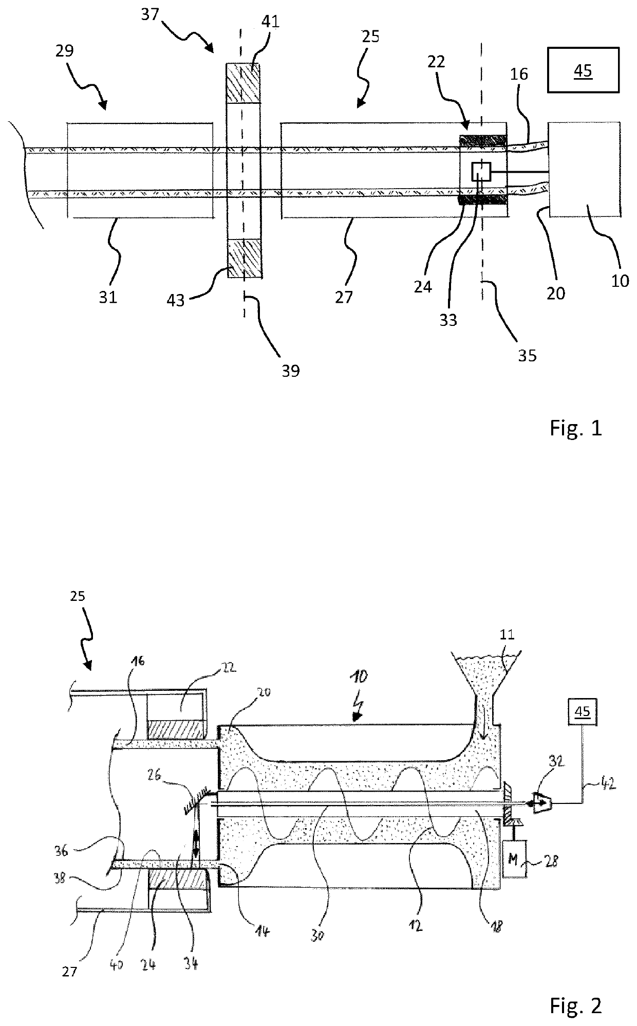
[0045]FIG. 1 shows an extruder 10 for extruding a tubular strand 16. In a manner known per se, the extruder 10 possesses a supply 11 for supplying the plastic material to be processed, which is shown for example in FIG. 2. The plasticized plastic material is extruded by an extruder screw 12 out of an annular gap 14 into a tubular strand 16. A rotationally driven central shaft 18 runs within the extruder screw 12. In the shown example, a calibration device 22 directly adjoins the extruder head 20 and has a metal calibration sleeve 24 against which the extruded strand 16 is pressed by means of a vacuum. The reference number 25 also shows a first cooling section 25 with a first cooling tube 27 in which a conducted cooling of the tubular strand 16 is carried out in such a way that the strand 16, after emerging from the first cooling section 25, has substantially concluded its shaping. Following the first cooling section 25 is a second cooling section 29 having a second cooling tube 31, ...


PUM

PropertyMeasurementUnit
outer diameteraaaaaaaaaa
wavelengthaaaaaaaaaa
circumferenceaaaaaaaaaa

Abstract

A device for measuring a strand that is tubular includes a first radiation source to emit terahertz radiation in a first measurement region from an inside onto an inner surface of the strand. A first radiation receiver receives terahertz radiation reflected by the strand in a second measurement region. A first evaluation apparatus determines at least one geometric parameter of the strand in the first measurement region. A second radiation source emits terahertz radiation in the second measurement region from an outside onto an outer surface of the strand. A second radiation receiver receives terahertz radiation reflected by the strand in the second measurement region. A second evaluation apparatus determines at least one geometric parameter of the strand in the second measurement region. A third evaluation apparatus determines a change in the at least one geometric parameter of the strand between the first and second measurement regions.

Description

CROSS REFERENCE TO RELATED INVENTION[0001]This application is a national stage application pursuant to 35 U.S.C. § 371 of International Application No. PCT / EP2020 / 065308, filed on Jun. 3, 2020, which claims priority to, and benefit of, German Patent Application No. 10 2019 119 491.1, filed Jul. 18, 2019, the entire contents of which are hereby incorporated by reference.FIELD OF TECHNOLOGY[0002]The invention relates to a method and a device for measuring a tubular strand emerging from an extruder and conveyed in a longitudinal direction.BACKGROUND[0003]In extruders, for example plastic that is supplied granulated is melted, and the flowable plastic is discharged as a tubular strand through an annular gap. Then the tubular strand enters a calibration device with a calibration sleeve, against the inner surface of which the tubular strand is pressed for example by applying a vacuum (vacuum tank). Subsequently, the tubular strand passes through one or more cooling sections in which the o...

Claims


Application Information

Patent Timeline
Patent Type & Authority Applications(United States)
IPC IPC(8): G01B15/02G01B15/04
CPCG01B15/02G01B15/04G01N21/3581B29C48/92B29C48/09B29C48/49B29C48/901G01N21/85G01B11/06B29C2948/92152B29C2948/92114B29L2023/22G01N2021/8416B29C48/90B29C48/21B29C2948/9219G01N2021/8557
Inventor HOLLE, ARMINFRANK, CHRISTIAN
Owner SIKORA AG
Why Eureka
Try Eureka