System and Method for RF Ablation with Generated Images of Ablated Tissue Lesions

a tissue lesions and rfa technology, applied in the field of system and method for visualizing an rfa procedure, can solve the problems of inability to propagate nerve impulses, difficult for a practitioner to determine exactly where the ablation is carried out, and slight difference in tissue density

Active Publication Date: 2019-02-14
VILIMS BRADLEY D
View PDF5 Cites 1 Cited by
  • Summary
  • Abstract
  • Description
  • Claims
  • Application Information

AI Technical Summary

Benefits of technology

[0034]According to yet another aspect of the invention, it may include generating dynamic virtual images of a lesion configuration as it is being created during a procedure. Arithmetic modeling can be provided in which a lesion size and shape can be incrementally shown on the user display to keep the practitioner advised as the ablation takes place. The dynamic virtual images could be progressive, time-based images in which the size of a selected lesion is shown to increase over time as RF energy conti

Problems solved by technology

The goal in these procedures is to sufficiently heat the nerves transmitting the pain signals so that the nerves are effectively ablated/coagulated and thus no longer capable of propagating a nerve impulse.
Further, the patient may only receive localized anesthesia which avoids general anesthesia and the risks associated therewith.
Despite the known use of imaging guidance to determine the desired position of the RFA probe, it may be difficult for a practitioner to determine exactly where the ablation takes place because the lesion to be created cannot be viewed.
Although there may be a slight difference in the density of the tissue after ablation, imaging technologies such as x-ray, ultrasound, and CT scans are not capable of effectively distinguishing between the ab

Method used


Image

  • System and Method for RF Ablation with Generated Images of Ablated Tissue Lesions
  • System and Method for RF Ablation with Generated Images of Ablated Tissue Lesions
  • System and Method for RF Ablation with Generated Images of Ablated Tissue Lesions

Examples


Embodiment Construction

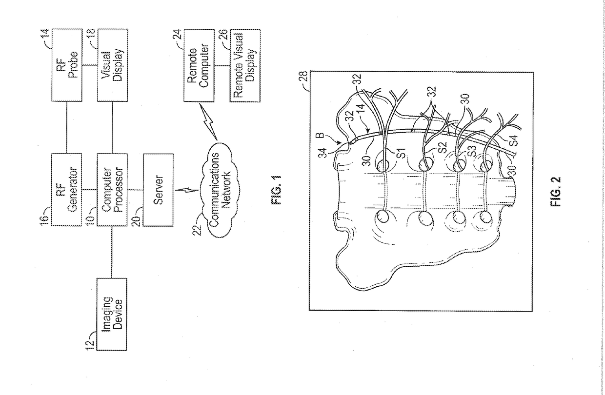
[0045]According to the system of the invention, the system produces virtual images of proposed and designated ablated tissue areas as oriented on a patient's anatomy. The virtual images include the size, shape, and location of ablated tissue areas for an RFA procedure. The virtual images may be supplemented with data such as a description of the size, shape and location of the ablated tissue areas.

[0046]Referring to a first preferred embodiment as illustrated in FIG. 1, the system includes a computer processor 10 that communicates with an imaging source, such as an X-ray, CT, or ultrasound imaging device 12. The imaging device 12 provides real time images of a patient's anatomy where the RFA procedure takes place. A practitioner inserts and positions a RF probe 14, under imaging guidance, at the location where treatment is to occur. The energy supplied to the RF probe 14 is a RF generator 16 that has a plurality of settings that allows the practitioner to select the amount and durat...


PUM


Abstract

The invention includes a system for generating virtual images of proposed and designated areas on a patient's anatomy that are to be treated in a RFA procedure. The images include a size, shape, and location of lesion/ablation patterns. The virtual images include dynamic (developing) or static (developed) lesions selected for the RFA procedure. The images are provided on at least one user interface that superimposes or overlays the lesion pattern(s) on an image of a patient's anatomy that undergoes the procedure. The images can be used to accurately and efficiently conduct RFA procedures and to record the procedures with enhanced visual data to confirm treated tissue areas. The invention further includes a diagnostic method of generating images in preparation for a RFA procedure, and a method of conducting the RFA procedure in which measured parameters determine the size and shape of the ablated areas achieved in the procedure.

Description

FIELD OF THE INVENTION[0001]The invention relates to radiofrequency ablation (RFA) and more specifically to a system and method for visualizing an RFA procedure to specifically show targeted areas of tissue for ablation. Images are generated that show lesion patterns created by the RFA procedures. The images enable medical personnel to better position an RFA device and to more accurately record where the RFA procedure took place.BACKGROUND OF THE INVENTION[0002]RFA or radiofrequency thermocoagulation neurotomy is a known medical procedure in which neural tissue is ablated using heat generated from a medium frequency alternating current generator. The energy is delivered by a radiofrequency probe or catheter placed within or adjacent to targeted tissue. The radiofrequency energy is then applied to the target tissue causing the tissue surrounding the probe to heat. The temperature attained within the tissue surrounding the radiofrequency probe is monitored via a thermocouple within th...

Claims


Application Information

Patent Timeline
IPC IPC(8): A61B18/14A61B34/10A61B90/00
CPCA61B18/14A61B34/10A61B90/37A61B2034/107A61B2017/00221A61B2018/00577A61B2034/105A61B2017/00199A61B18/1206A61B2018/00434A61B2018/0044A61B2018/00714A61B2018/0072A61B2018/00761A61B2018/00767A61B34/25A61B2090/364A61B2090/376A61B2090/3762A61B2090/378A61B2018/00791A61B2018/00821A61B2018/00875
Inventor VILIMS, BRADLEY D.
Owner VILIMS BRADLEY D
Why Eureka
Try Eureka