Cylinder sleeve

a technology of cylinder sleeves and sleeve covers, which is applied in the direction of reciprocating piston engines, positive displacement engines, cylinders, etc., can solve the problems of local disruption of heat transfer between the cylinder sleeves and the crankcase, non-uniform inability to produce with as little effort, etc., to achieve uniform temperature distribution in the cylinder, reliable shape fitting, and the effect of producing with as little effor

Active Publication Date: 2014-05-13
MAHLE INT GMBH
View PDF10 Cites 2 Cited by
  • Summary
  • Abstract
  • Description
  • Claims
  • Application Information

AI Technical Summary

Benefits of technology

[0009]The task of the present invention therefore consists in making available a cylinder sleeve having an outer mantle surface that has a surface structure, which can be produced with as little effort as possible, and nevertheless guarantees reliable shape fit as well as the greatest possible heat transfer to the crankcase, and thus a uniform temperature distribution in the cylinder.
[0011]It has surprisingly been found that it is sufficient to provide only some of the elevations with at least one undercut. By means of this measure, a very good mechanical clamping effect is achieved, and gap formation between the materials of the cylinder sleeve and of the crankcase is reliably avoided. The heat-conducting contact between cylinder sleeve and crankcase is also very uniform, with very good heat transfer, since the increase in size of the effective surface area of the cylinder sleeve is sufficient, without every elevation having to be provided with undercuts. The heat that occurs in the combustion chamber of the engine can therefore be easily passed on to the cooling water through the cylinder wall. The holding force of the cylinder sleeve in the crankcase, in the tangential direction, is also extremely satisfactory. The inner machining of the cylinder sleeve, which follows by cutting after the sleeve is cast in, can be carried out at a clearly higher cutting power, without the cylinder sleeve turning out of its original position. Since fewer undercuts have to be produced, the production of the cylinder sleeve according to the invention is less complicated. It was also surprisingly found that as the result of the formation of rounded areas in the region of the base of each elevation, the tools required for this purpose are subject to less stress and their useful lifetime is significantly improved. The cylinder sleeve according to the invention therefore combines the demands with regard to very good shape fit in the crankcase and the demands with regard to production that is not very complicated, in a particularly efficient manner.
[0014]The elevations with undercuts preferably have a radial height between 0.7 and 1.6 mm, which is greater, in each instance, than the radial heights of the elevations without undercut. In this way, the shape fit between cylinder sleeve and crankcase is further improved. This result can also be achieved or reinforced in that the radial heights of the elevations with undercut are dimensioned to be greater by a factor of 1.5 to 15 than the radial heights of the elevations without undercut.
[0016]The elevations can furthermore be configured over a partial region of the outer mantle surface, in the axial direction. In this way, production is further simplified, and the production time is shortened, without any significant losses in the shape fit and in the heat conduction capability taking place. For example, the elevations can be configured in the center region of the outer mantle surface.
[0017]The elevations can furthermore have at least one run-in zone and / or at least one run-out zone, so that the material of the crankcase can sheathe the elevations without problems and completely when the cylinder sleeve is cast in.
[0018]It is advantageous if the elevations are produced using a cutting method, since the tools required for this are subject to less stress than before, because of the reduced production effort.

Problems solved by technology

It proves to be disadvantageous, in this connection, that gaps or interstices can form between the cylinder sleeve and the material of the crankcase, in the radial direction, as the result of tensile stress.
As a result, local disruptions of the heat transfer between cylinder sleeve and crankcase can occur during engine operation.
This results in a non-uniform temperature distribution in the cylinder, which in turn can lead to cylinder distortions, i.e. to deformation of the cylinders.
Therefore the seal of the combustion chamber situated above the piston head, by means of the piston rings, is also impaired.
However, this leads to increased friction power and thus to increased fuel consumption during engine operation.
However, the production of such surface structures by means of forming methods is very complicated.
Production by means of cutting work has the disadvantage that a suitable contour tool is required for this purpose, in order to achieve the desired undercuts.
Furthermore, it has been shown that such tools wear out too fast, due to local overheating, particularly in the corner region.

Method used


Image

  • Cylinder sleeve
  • Cylinder sleeve
  • Cylinder sleeve

Examples


Embodiment Construction

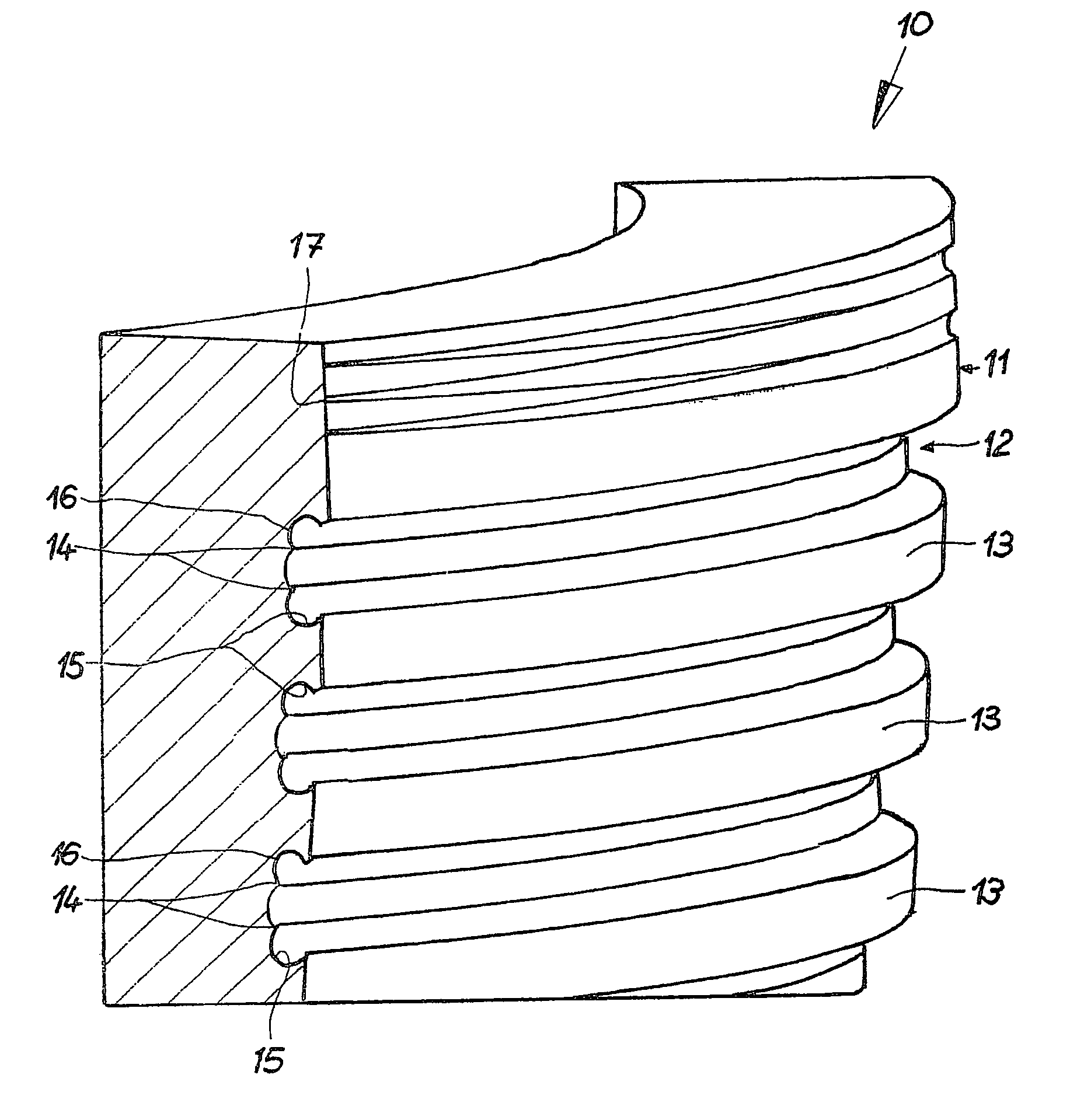
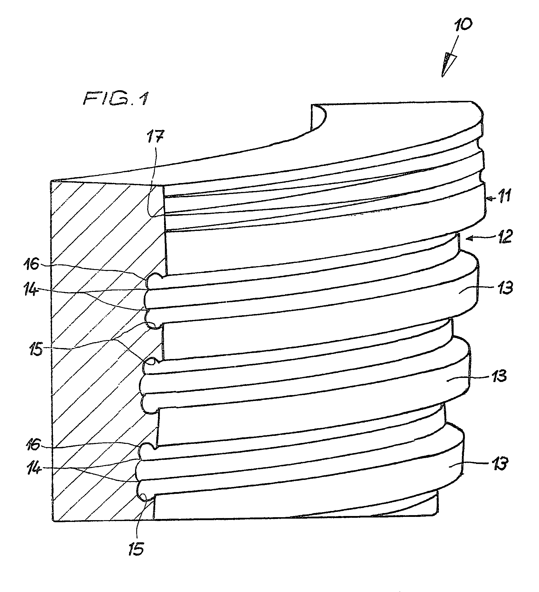
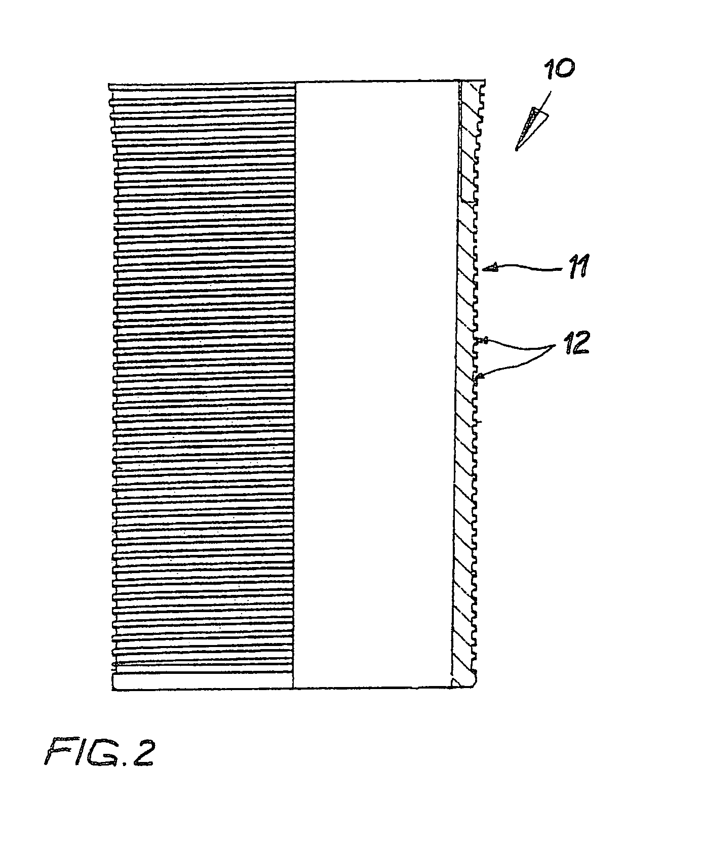
[0026]FIGS. 1 to 3 show a first exemplary embodiment of a cylinder sleeve 10 according to the invention, having a surface structure 12 according to the invention. The cylinder sleeve 10 is produced from cast iron, for example, or from a wear-resistant aluminum alloy. The outer mantle surface 11 of the cylinder sleeve 10 can be configured to be partly narrowed and / or partly widened and / or oval in cross-section. In the exemplary embodiment, the outer mantle surface 11 is provided with a surface structure 12 that runs in spiral shape, at a uniform incline. FIG. 2 shows the cylinder sleeve in an overall view, whereby the left half shows a front view and the right half shows a sectional representation. In the exemplary embodiment, the entire mantle surface 11 of the cylinder sleeve 10 is provided with a surface structure 12. Of course, the surface structure 1 can also be configured only in the axial direction, over a partial region of the outer mantle surface 11, for example in the cente...


PUM


Abstract

The present invention relates to a cylinder sleeve (10) having an outer mantle surface (11) that has a surface structure (12, 112, 212). According to the invention, it is provided that the mantle surface (11) is provided with elevations (13, 113, 213; 14, 118, 219), that each elevation (13, 113, 213; 14, 118, 219) has at least one rounded area (16, 116, 216) in the region of its base (B), that some of the elevations (13, 113, 213) have at least one undercut (15, 115, 215), and that at least one elevation (14, 118, 219) without undercut is disposed between two elevations (13, 113, 213) with undercut (15, 115, 215).

Description

CROSS REFERENCE TO RELATED APPLICATIONS[0001]Applicants claim priority under 35 U.S.C. §119 of German Application No. 10 2009 056 919.7 filed Dec. 3, 2009, the disclosure of which is incorporated by reference.BACKGROUND OF THE INVENTION[0002]1. Field of the Invention[0003]The present invention relates to a cylinder sleeve having an outer mantle surface that has a surface structure.[0004]Cylinder sleeves for internal combustion engines are generally cast together with the crankcase. For this purpose, the cylinder sleeves are placed into a casting mold and the material of the crankcase is cast around them.[0005]For the production of a crankcase for internal combustion engines, composed of a light metal material, generally ductile and high-strength aluminum alloys are used. The cylinder sleeves preferably consist of cast iron or a wear-resistant aluminum alloy. In this connection, however, no material-fit connection between the materials, i.e. no metallic bond between the material of t...

Claims


Application Information

Patent Timeline
Patent Type & Authority Patents(United States)
IPC IPC(8): F16J10/04
CPCF02F1/18F16J10/04F02F1/20F05C2251/048
Inventor BISCHOFBERGER, ULRICHGAISELMANN, STEFAN
Owner MAHLE INT GMBH
Why Eureka
Try Eureka