Supercharge Your Innovation With Domain-Expert AI Agents!

Self-calibrating linear voltage differential transformer demodulator

a transformer demodulator and linear voltage technology, applied in process and machine control, process control, instruments, etc., can solve the problems of difficult peak-to-peak measurement determination and many samples to measure the magnitude correctly

Active Publication Date: 2018-11-20
GOODRICH AEROSPACE SERVICES PTE LTD +1
View PDF19 Cites 0 Cited by
  • Summary
  • Abstract
  • Description
  • Claims
  • Application Information

AI Technical Summary

Problems solved by technology

Moreover, if the excitation waveform has distortion from an ideal sine wave, the measurement will require many samples to measure the magnitude correctly.
The challenge of this peak-to-peak measurement is to find the peaks of the secondary waveform.
This phase shift changes as a function of the temperature, aging, interconnect wiring etc., making determination of the peak-to-peak measurement difficult.

Method used


Image

  • Self-calibrating linear voltage differential transformer demodulator
  • Self-calibrating linear voltage differential transformer demodulator
  • Self-calibrating linear voltage differential transformer demodulator

Examples


Embodiment Construction

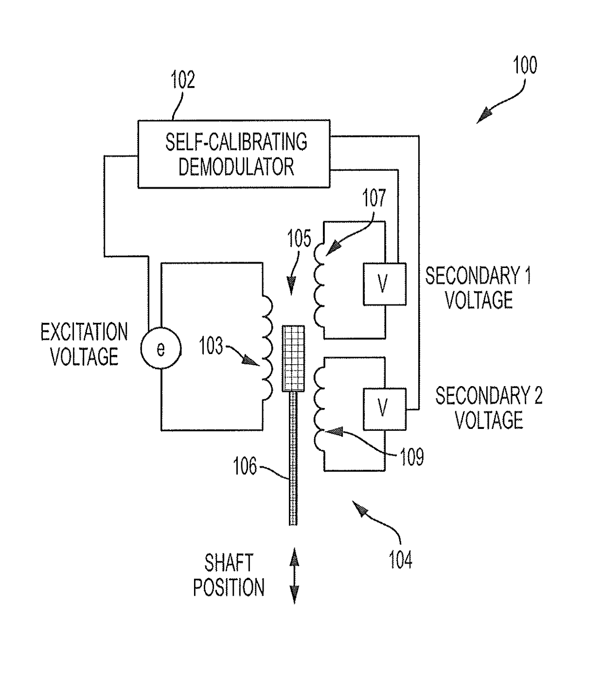
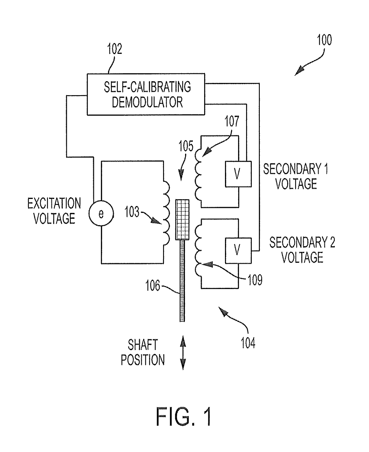
[0011]FIG. 1 illustrates a view of a position sensor 100 including a self-calibrating demodulator 102 of the subject invention. The position sensor 100 includes a linear voltage differential transformer (LVDT) 104. The position sensor 100 measures a relative position of a movable shaft 106 located between a primary winding 103 and the secondary windings 105 of the LVDT. The voltages across the secondary windings 105 are used to determine the position of the movable shaft 106. The position of the movable shaft 106 is calculated based on ratio of the peak-to-peak voltages of the secondary windings 105. Specifically, the following formula can be used to calculate relative position of the movable shaft 106:

[0012]P=(Vsec⁢⁢1-Vsec⁢⁢2)(Vsec⁢⁢1+Vsec⁢⁢2)

[0013]In the above equation, P is the relative position, Vsec1 is a first voltage across the first secondary winding 107, and Vsec2 is a second voltage across the second secondary winding 109. For accuracy, it may be desirable to represent Vse...


PUM


Abstract

A calibration system includes an excitation module that introduces an excitation signal to a primary coil of a differential transformer, a measurement module that measures, at a first phase shift, a positive value of an induced signal. The induced signal is caused by the excitation signal on a secondary coil of the differential transformer. The system further includes a calculation module that compares the positive value to a last positive value to form a compared positive value, and a calibration module that changes the first phase shift based on the compared positive value.

Description

FIELD OF THE INVENTION[0001]The subject matter disclosed herein relates to aircraft actuation systems, and in particular to a self-calibrating linear voltage differential transformer demodulator.BACKGROUND[0002]A linear voltage differential transformer position sensor can sense a position of a shaft disposed between a primary winding and secondary windings of the transformer. An excitation signal is applied to the primary winding, and the excitation signal is coupled to the secondary windings. The resulting voltages across the secondary windings can be used to calculate shaft position. One technique to measure the secondary voltages involves calculating the RMS or average value across each secondary winding in response to the excitation signal applied to the primary winding. This method requires collecting several samples during the period of the excitation frequency. Moreover, if the excitation waveform has distortion from an ideal sine wave, the measurement will require many sampl...

Claims


Application Information

Patent Timeline
Patent Type & Authority Patents(United States)
IPC IPC(8): G01R35/00G01R33/00G01D5/22G01D5/20G01D18/00
CPCG01D18/00G01D5/20G01D5/2291G01R33/0035G01R33/0017G05B2219/37185G05B2219/37124
Inventor RONNING, ERIC DUANENINJURI, NATRAJRAO, KALLURI
Owner GOODRICH AEROSPACE SERVICES PTE LTD
Features
  • R&D
  • Intellectual Property
  • Life Sciences
  • Materials
  • Tech Scout
  • Unparalleled Data Quality
  • Higher Quality Content
  • 60% Fewer Hallucinations
Learn More