Arrangement for level measurement

a level measurement and arrangement technology, applied in the direction of level indicators by pressure measurement, heat exchanger types, heat storage plants, etc., can solve the problem of complicated attachment of the measuring device to the container

Active Publication Date: 2018-11-20
MARQUARDT GMBH SCHLOSSTRASSE 16 7201 RIETHEIM-WEILHEIM 1 WEST GERMANY
View PDF15 Cites 0 Cited by
  • Summary
  • Abstract
  • Description
  • Claims
  • Application Information

AI Technical Summary

Benefits of technology

[0010]In a simple and economical configuration of the present invention, the dynamic pressure probe can comprise a pipe. Expediently, the one end of the pipe can be fixed to the conduit, specifically fixed in a fluid-tight manner to the wall of the conduit. Such a fluid-tight fixing can be implemented, for example, by means of welding, soldering, adhesive bonding or the like. The other end of the pipe can be arranged such that the end penetrates the conduit. The pressure sensor can be arranged at the other end on the opening of the pipe. Preferably an arrangement is provided such that the pressure sensor is located outside of the conduit. The pressure sensor can have a housing in the usual way to protect the sensor. Furthermore, a diaphragm can be arranged in and / or on the housing for the purpose of sealing. In a functionally reliable way, a resilient element for resetting the diaphragm can be provided. In order to generate the pressure signal, a signal transmitter can be operatively connected to the diaphragm and / or the resilient element, and / or a signal receiver can interact with the signal transmitter.
[0011]In order to reduce the installed height of the pressure sensor, it may be worthwhile to configure the resilient element in the manner of a disk-like leaf spring. Expediently, the leaf spring can have a circular shape which corresponds substantially to the shape of the diaphragm. A particularly high resetting force can be achieved in the case of the resilient element by the leaf spring having a spring element extending spirally from the center to the edge region of the leaf spring. This ensures a compact configuration with a high spring force. For the purpose of simple and economical production, the resilient element can be produced from metal as a punched part.
[0012]In a simple and economical configuration of the present invention, the signal transmitter can comprise a magnet. The signal receiver can comprise a position sensor, which detects the magnetic field generated by the magnet. The position sensor can economically be a Hall sensor. It may be worthwhile simply to arrange the signal transmitter on the resilient element, specifically, in the center of the resilient element. In order to prevent any displacement between the magnet and the spring, the signal transmitter can expediently be adhesively bonded to the resilient element.

Problems solved by technology

Here, the attachment of the measuring device to the container is complicated.

Method used


Image

  • Arrangement for level measurement
  • Arrangement for level measurement
  • Arrangement for level measurement

Examples


Embodiment Construction

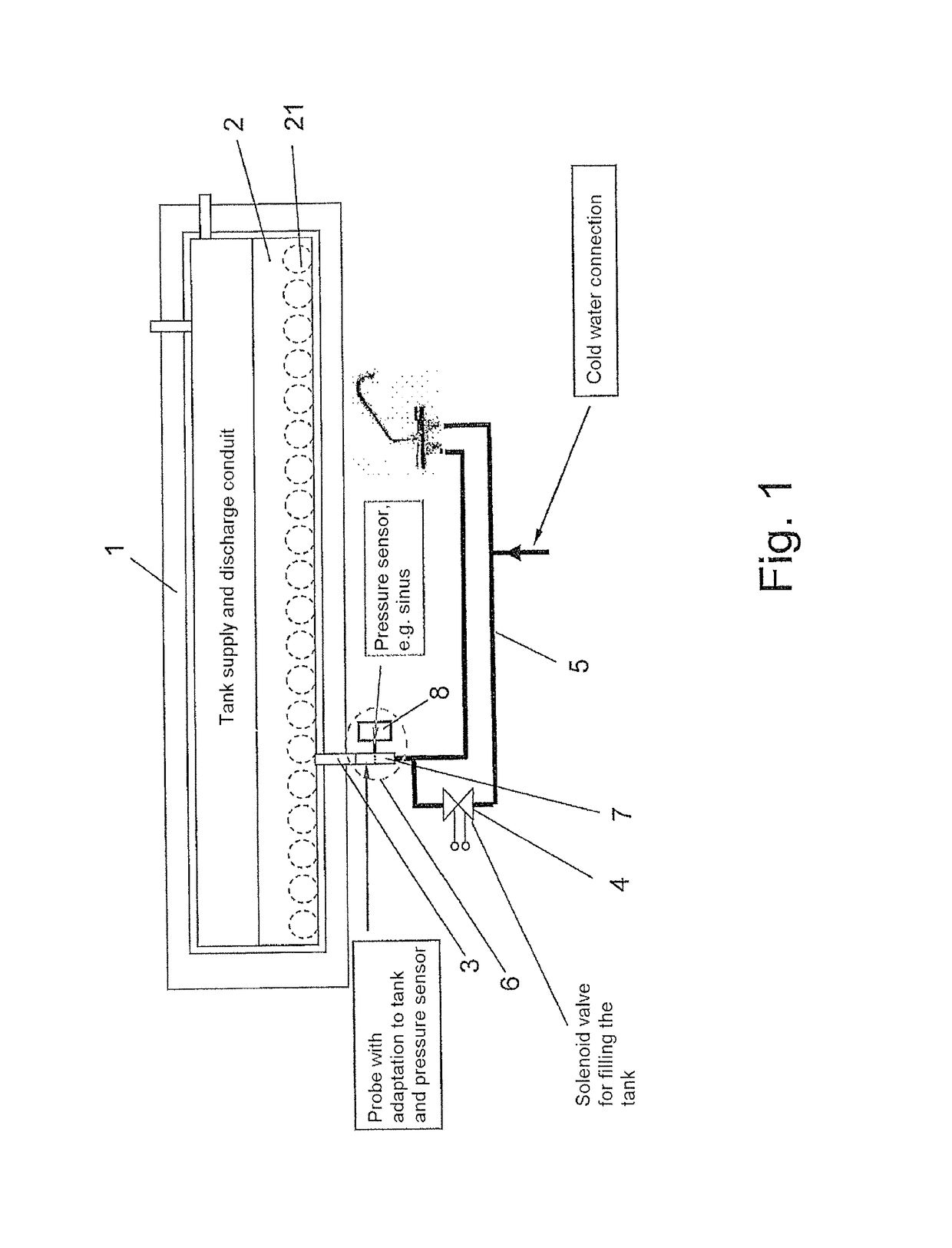
[0028]FIG. 1 reveals a container 1 for holding a fluid 2, specifically in the present case, the container 1 is used to hold solar-heatable water 2 (solar water heater). In order to heat the water 2, there are in the container 1 pipes 21 connected to the solar collector and arranged in the form of loops for the heat exchange medium. The container 1 is provided with a single conduit 3, comprising a pipe, for the supply and / or removal of the fluid 2. The conduit 3 is in turn connected via a controllable solenoid valve 4 to a water supply system 5 for the building. By means of appropriate activation of the solenoid valve 4, the container 1 can thus be filled with cold water 2 from the water supply system 5. The warm water 2 heated by means of solar energy and located in the container 1 can be fed in a corresponding way to the water supply system 5 in the building.

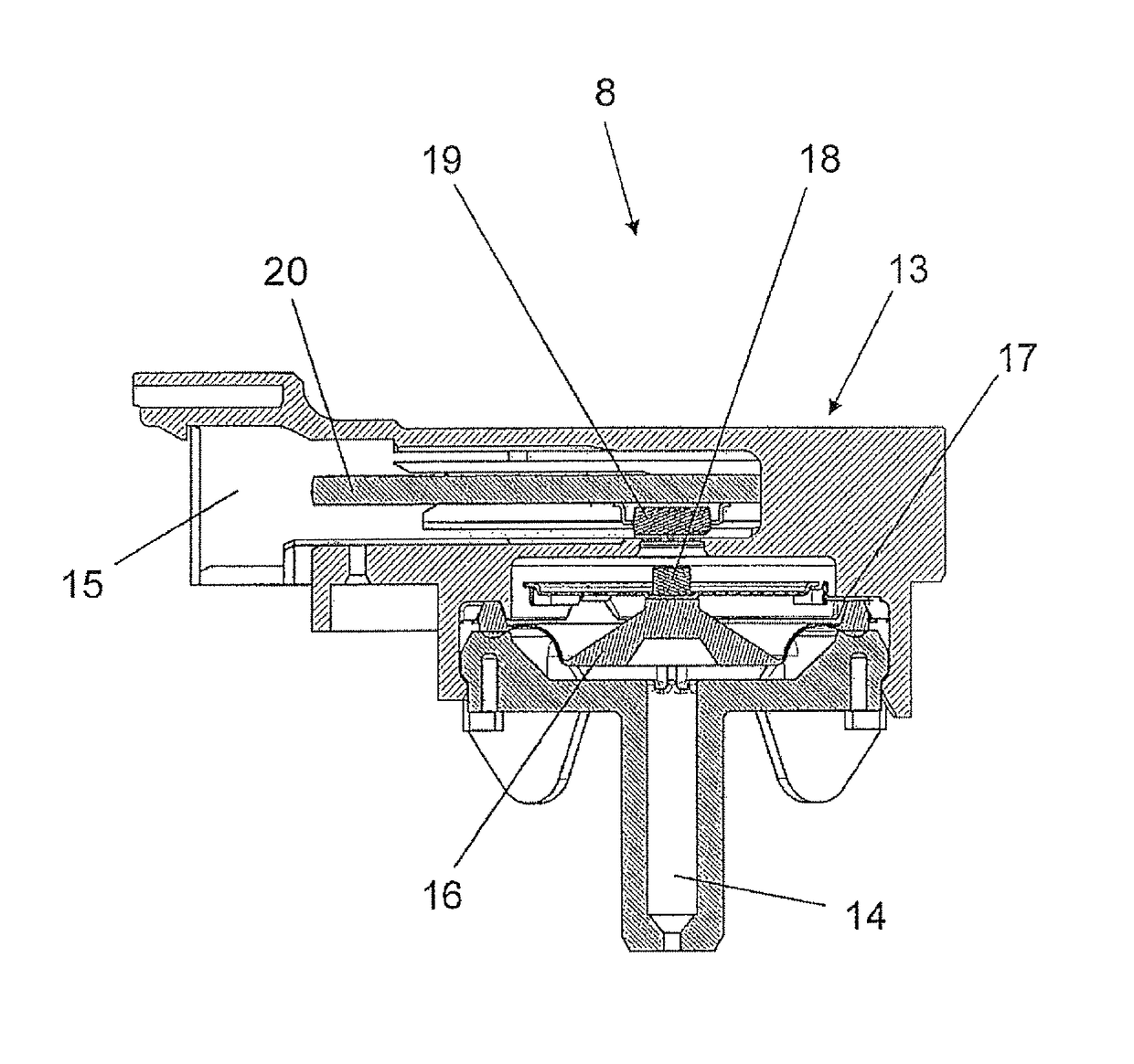
[0029]Provided on the container 1 is a measuring device, such as level sensor 6, for measuring the level of the fluid in the ...


PUM


Abstract

The invention relates to a measuring device for measuring a level of a fluid in a container for holding a fluid, specifically a level sensor. The container is provided with a conduit for at least one of the supply and the removal of the fluid. A dynamic pressure probe, such as a pitot tube, is arranged in the conduit. The dynamic pressure probe is connected to a pressure sensor for measuring the pressure in the dynamic pressure probe. The fluid level in the container can be determined by using the measured pressure.

Description

CROSS-REFERENCE TO RELATED APPLICATION[0001]This application claims the benefit under 35 USC § 119(a)-(d) of German Application No. 10 2013 007 020.1 filed Apr. 24, 2013.BACKGROUND OF THE INVENTION[0002]1. Field of the Invention[0003]The present invention relates to a measuring device.[0004]2. Description of Related Art[0005]Such a measuring device is used for level measurement in a container. In particular, this measuring device is a level sensor.[0006]On a container for holding a fluid, for example, water, it is known to provide a measuring device for measuring the level for the fluid in the container. The container, configured in the manner of a tank, is provided with a conduit, comprising a pipe, for example, for the supply and / or removal of the fluid. For simplicity, the filling and / or emptying of the container can take place via the only one conduit, which is attached to the underside of the container. Here, the attachment of the measuring device to the container is complicate...

Claims


Application Information

Patent Timeline
Patent Type & Authority Patents(United States)
IPC IPC(8): G01F23/16G01F23/14F28D20/00
CPCG01F23/14F28D20/0034Y02E60/142F28D2020/0078Y02E60/14
Inventor ZIMMER, ANDREASJAUCH, TOBIAS
Owner MARQUARDT GMBH SCHLOSSTRASSE 16 7201 RIETHEIM-WEILHEIM 1 WEST GERMANY
Why Eureka
Try Eureka