Method for manufacturing three-dimensional structure, method for manufacturing scintillator panel, three-dimensional structure, and scintillator panel

a three-dimensional structure and scintillator technology, applied in the direction of instruments, nuclear engineering, conversion screens, etc., can solve the problems of luminance drop and luminance decrease, and achieve high precision, high brightness and clear image. , the effect of large area

Active Publication Date: 2018-11-20
TORAY IND INC
View PDF17 Cites 2 Cited by
  • Summary
  • Abstract
  • Description
  • Claims
  • Application Information

AI Technical Summary

Benefits of technology

[0010]However, in the conventional method for manufacturing a scintillator panel using a glass powder-containing paste, since a pattern including the glass powder-containing paste is formed on a substrate and then the glass powder is sintered by firing to forma barrier rib, it is needed to select, as the substrate, a highly heat-resistant substrate that cannot be burned down or cannot be highly deformed during the firing step. Furthermore, it is also needed to secure the strength of the substrate for preventing the warpage of the substrate during firing, and therefore it is needed to use a thick substrate for securing the high strength of the substrate. As a substrate having high heat resistance and high strength, a substrate mainly made from an inorganic material, e.g., a glass substrate and a ceramic substrate, can be mentioned. However, the substrate made from an inorganic material can absorb X-ray easily, and therefore has a problem that X-ray is absorbed by the substrate before the X-ray reaches a phosphor, resulted in the decrease in luminance. The substrate has a low reflectance, and therefore also has a problem that light emitted upon scintillation is leaked to the substrate side, resulted in the decrease in luminance.
[0011]Thus, the object of the present invention is to provide: a method for manufacturing a three-dimensional structure and a three-dimensional structure; and a method for manufacturing a scintillator panel and a scintillator panel, in which the three-dimensional structure is used and the type and thickness of a substrate for the scintillator panel can be selected freely.
[0043]According to the method for manufacturing a three-dimensional structure and the three-dimensional structure of the present invention, it is possible to place a barrier rib having a narrow width on a desired substrate over a large area and with high precision. Therefore, it is possible to select a proper substrate without the limitation with respect to heat resistance and strength, and it is also possible to place a barrier rib having a narrow width on the substrate. That is, a method for manufacturing a scintillator panel whereby a highly bright and clear image can be obtained and a scintillator panel can be provided.

Problems solved by technology

However, in the conventional method for manufacturing a scintillator panel using a glass powder-containing paste, since a pattern including the glass powder-containing paste is formed on a substrate and then the glass powder is sintered by firing to forma barrier rib, it is needed to select, as the substrate, a highly heat-resistant substrate that cannot be burned down or cannot be highly deformed during the firing step.
However, the substrate made from an inorganic material can absorb X-ray easily, and therefore has a problem that X-ray is absorbed by the substrate before the X-ray reaches a phosphor, resulted in the decrease in luminance.
The substrate has a low reflectance, and therefore also has a problem that light emitted upon scintillation is leaked to the substrate side, resulted in the decrease in luminance.

Method used


Image

  • Method for manufacturing three-dimensional structure, method for manufacturing scintillator panel, three-dimensional structure, and scintillator panel
  • Method for manufacturing three-dimensional structure, method for manufacturing scintillator panel, three-dimensional structure, and scintillator panel
  • Method for manufacturing three-dimensional structure, method for manufacturing scintillator panel, three-dimensional structure, and scintillator panel

Examples


example 1

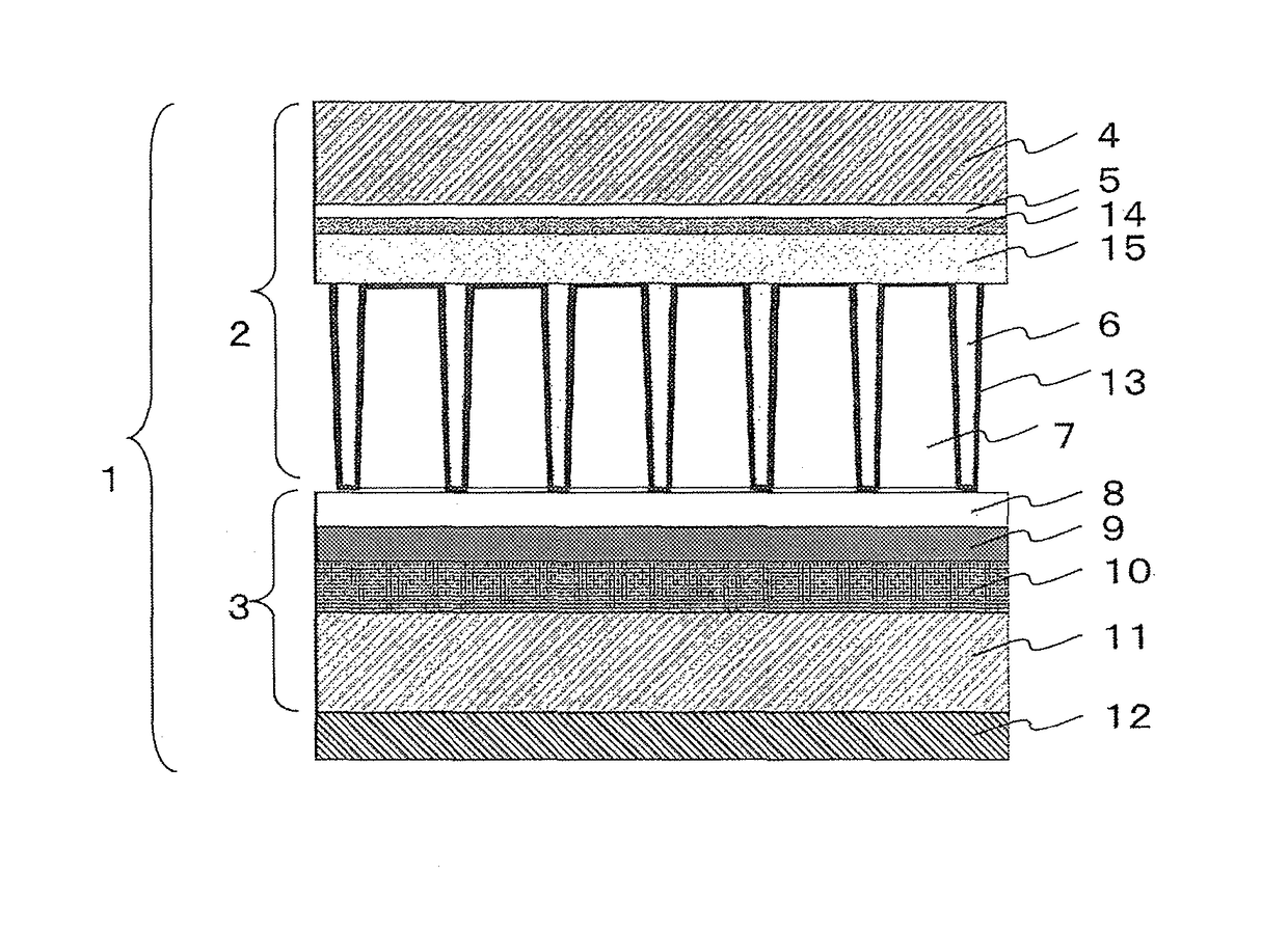
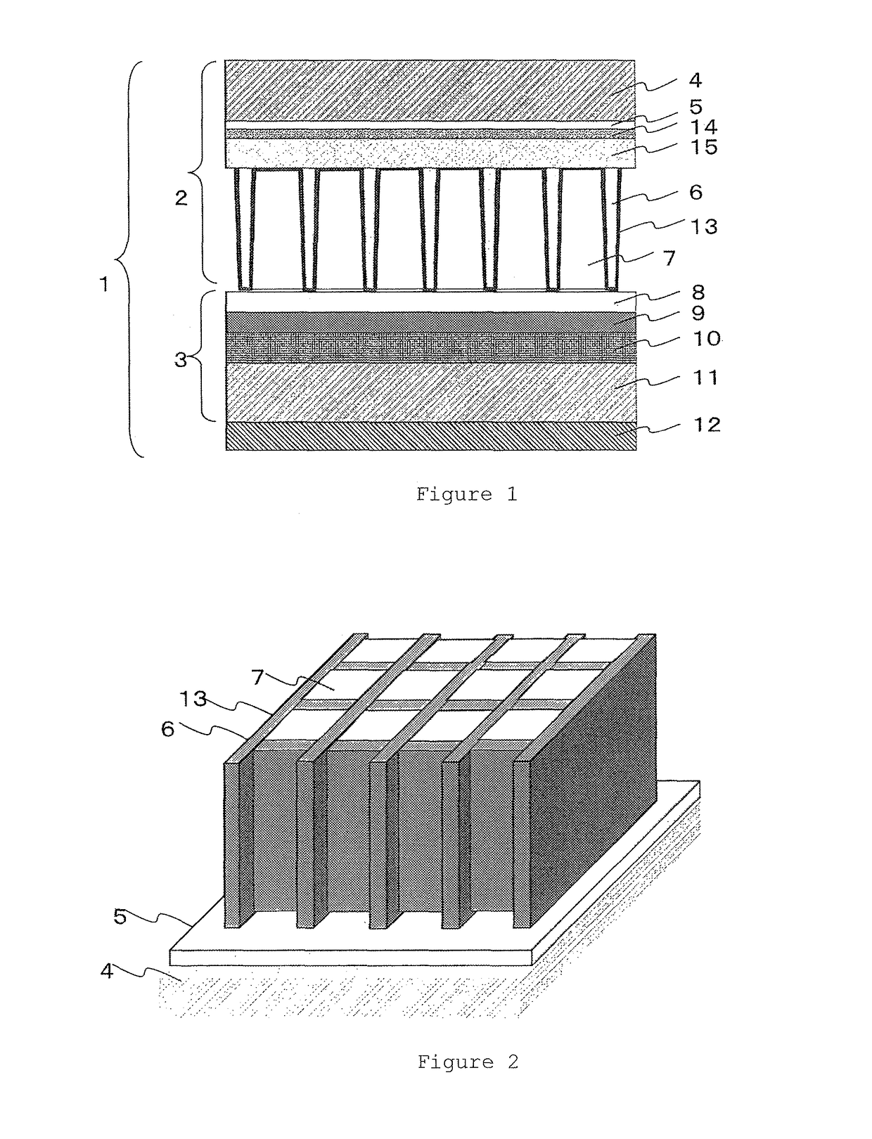
[0208]As the base member, a glass plate having a size of 500 mm×500 mm×1.8 mm (PD-200; Asahi Glass Co. Ltd., linear expansion coefficient: 83×10−7 (K−1)) was used. The non-sinterable paste 1 was applied onto the surface of the base member with a die coater in such a manner that the resultant film could have a thickness of 50 μm after drying, and then the resultant film was dried to form a separation aid layer. The glass powder-containing paste A was applied onto the surface of the separation aid layer with a die coater in such a manner that the resultant film could have a thickness of 500 μm after drying, and then the resultant film was dried to produce a coating film A. Subsequently, the coating film A was exposed to light at a light exposure amount of 750 mJ / cm2 with an ultra-high-pressure mercury lamp through a photomask having an opening corresponding to a desired pattern (a chrome mask having a grid-like opening with a pitch of 125 μm and a line width of 20 μm). The exposed coa...

example 2

[0212]The examination was carried out in the same manner as in Example 1, except that an alumina substrate (reflectance: 70%) having a size of 500 mm×500 mm×0.3 mm was used as the substrate. The relative value of the luminance was 80 relative to the luminance (i.e., 100) achieved in Example 1, and was therefore good. The image sharpness was also good.

example 3

[0213]The examination was carried out in the same manner as in Example 1, except that PD-200 (reflectance: 15%) which had been ground to a thickness of 0.7 mm was used as the substrate. The relative value of the luminance was 50 relative to the luminance (i.e., 100) achieved in Example 1, and was therefore relatively good. The image sharpness was also good.


PUM

PropertyMeasurementUnit
reflectanceaaaaaaaaaa
wavelengthaaaaaaaaaa
softening temperatureaaaaaaaaaa

Abstract

The purpose of the present invention is to provide a method for manufacturing a three-dimensional structure, a method for manufacturing a scintillator panel, a three-dimensional structure, and a scintillator panel that enable the type and thickness of a substrate of the scintillator panel to be selected freely. The present invention provides a method for manufacturing a three-dimensional structure, by which a three-dimensional structure is obtained by forming a glass pattern on a base member and then separating the glass pattern from the base member.

Description

CROSS REFERENCE TO RELATED APPLICATIONS[0001]This is the U.S. National Phase application of PCT / JP2014 / 079217, filed Nov. 4, 2014, and claims priority to Japanese Patent Application No. 2013-230133, filed Nov. 6, 2013, the disclosures of each of these applications being incorporated herein by reference in their entireties for all purposes.FIELD OF THE INVENTION[0002]The present invention relates to a method for manufacturing a three-dimensional structure, a method for manufacturing a scintillator panel, a three-dimensional structure, and a scintillator panel.BACKGROUND OF THE INVENTION[0003]Conventionally, X-ray images using films have been widely used in medical settings. However, an X-ray image using a film provides analog image information. Then, in recent years, digital-mode radiation detectors, such as computed radiography (CR) and flat panel radiation detectors (FPDs), have been developed.[0004]In an FPD, a scintillator panel is used for converting a radioactive ray to visible...

Claims


Application Information

Patent Timeline
Patent Type & Authority Patents(United States)
IPC IPC(8): G01T1/20C03C17/04C03C8/16G21K4/00
CPCG01T1/2002C03C8/16G01T1/20G21K4/00C03C17/04G21K2004/06C03C17/002
Inventor TANINO, TAKAHIROHAMANO, TSUBASAFUJIOKA, NOBUYASU
Owner TORAY IND INC
Why Eureka
Try Eureka