Cover unit with rubber plug and connector

a technology of rubber plugs and connectors, applied in the direction of couplings/cases, coupling device connections, testing/measuring connectors, etc., can solve the problems of high degree of difficulty in assembly, easy disassembly, and easy disassembly of the sealing plug body, so as to improve assembling efficiency and improve assembly efficiency. , the effect of improving the assembling efficiency

Active Publication Date: 2018-11-20
SUMITOMO WIRING SYST LTD
View PDF14 Cites 2 Cited by
  • Summary
  • Abstract
  • Description
  • Claims
  • Application Information

AI Technical Summary

Benefits of technology

[0006]According to this configuration, the recess of the leg long in the radial direction. Thus, the peripheral wall of the recess will not interfere with the projection to obstruct a returning movement of the leg when the leg returns and the recess is fit to the projection. Specifically, since the recess can be fit to the projection only by a reaction force (force trying to return to a natural state) of the rubber plug, it is not necessary to fit the recess to the projection by forcibly deforming or pulling the leg and assembling efficiency can be improved drastically improved.
[0007]A tapered portion may be provided between a locking portion of the projection facing an inner wall of the recess and the assembling hole and may be configured not to obstruct a returning movement of the leg. According to this configuration, there is nothing that obstructs the returning movement of the leg until the leg contacts the tapered portion after being inserted into the assembling hole, and the leg is in an open state when contacting the tapered portion. Thus, the reaction force of the rubber plug easily acts in a direction to assemble the rubber plug with the rubber plug holder.
[0008]The projection may be tapered by a plurality of the tapered portions. According to this configuration, the projection is fit easily into the recess.
[0009]According to the rubber plug assembly disclosed by this specification, it is possible to improve assembling efficiency in assembling the rubber plug with the rubber plug holder.

Problems solved by technology

Thus, the sealing plug body is detached easily and is difficult to position even if being directly mounted on the voltage detection cover.
However, to assemble a rubber component such as the sealing plug body with the resin component, it is necessary to forcibly deform and pull the rubber component.
Therefore a degree of difficulty in assembling is high.

Method used


Image

  • Cover unit with rubber plug and connector
  • Cover unit with rubber plug and connector
  • Cover unit with rubber plug and connector

Examples


Embodiment Construction

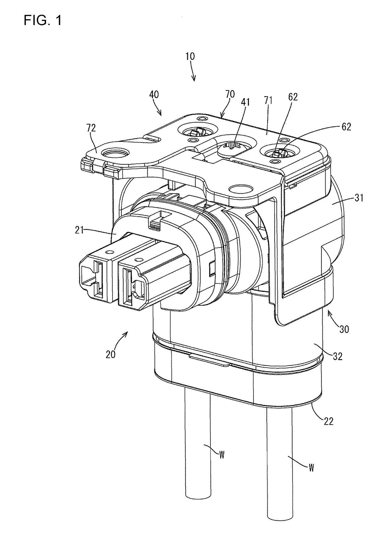
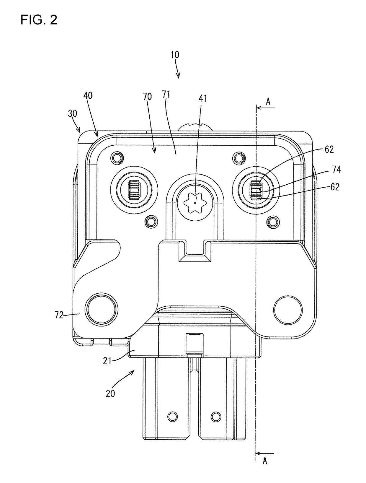
[0026]An embodiment is described with reference to FIGS. 1 to 16. A connector 10 of this embodiment includes a housing 20 made of synthetic resin and a shield shell 30 made of metal for covering the housing 20, as shown in FIG. 1. The housing 20 is substantially L-shaped and includes a connector fitting portion 21 that projects forward and a wire pull-out portion 22 from which wires W are pulled out downwardly. The connector fitting portion 21 is fittable into a mounting hole provided in a casing of an unillustrated device. The shield shell 30 includes an upper shell 31 for covering the connector fitting portion 21 and a lower shell 32 for covering the wire pull-out portion 22.

[0027]A rubber plug assembly 40 is attached to an upper part of the upper shell 31. As shown in FIGS. 4 and 5, the rubber plug assembly 40 is formed by integrally assembling rubber plugs 50, rubber plug holders 60 made of synthetic resin and a cover 70 made of metal. One rubber plug 50 and one rubber plug hold...


PUM


Abstract

A rubber plug assembly (40) includes a rubber plug (50) with a shaft (51) and waterproofs the interior of a housing (20). Legs (52) extend out in a radial direction from an axial end (51A) of the shaft (51). Recesses are in the legs (52) and are long in the radial direction. A cover (70) is to be fixed to the housing (20). A rubber plug holder (60) includes assembling holes (65) for allowing the legs (52) oriented in an axial direction to be inserted therein by resiliently deforming parts of the legs (52) and projections (66) for positioning the rubber plug (50) by being fit into the recesses as the legs (52) that have passed through the assembling holes (65) return. The projections (66) and the recesses are held in a fit state by fixing the rubber plug holder (60) to the cover (70).

Description

BACKGROUNDField of the Invention[0001]This specification relates to a rubber plug assembly.Description of the Related Art[0002]Japanese Unexamined Patent Publication No. 2015-82465 discloses a connector to be connected to a large-current cable. This connector includes a housing that can fit into a mounting hole in a casing of a device. The inside of the housing includes a device-side terminal to be connected to a mating terminal, a wire-side terminal connected to a core of a wire, and a connecting member that connects the device-side terminal and the wire-side terminal. Voltage detection holes are open in an upper part of the housing and expose a connecting part of a connection terminal and the wire-side terminal. The voltage detection holes correspond to a positive electrode and a negative electrode for enabling respective lead rods of a tester to contact the connecting part of the connection terminal and the wire-side terminal to confirm that the connecting part of the connection ...

Claims


Application Information

Patent Timeline
Patent Type & Authority Patents(United States)
IPC IPC(8): H01R13/44H01R13/52
CPCH01R13/44H01R13/5202H01R13/52H01R13/5213H01R2201/20H01R2201/26
Inventor KASHIWADA, TOMOKAZU
Owner SUMITOMO WIRING SYST LTD
Why Eureka
Try Eureka