
Stator of motor for washing machine

a technology for washing machines and stabilizers, which is applied in the direction of dynamo-electric machines, magnetic circuit shapes/forms/constructions, supports/encloses/casings, etc., can solve the problems of noise generation, noise generation, noise and increase of manufacturing costs, and structure may generate noise, etc., to reduce manufacturing costs and prevent noise and vibration.

Active Publication Date: 2018-11-20
NEW MOTECH
View PDF16 Cites 3 Cited by
  • Summary
  • Abstract
  • Description
  • Claims
  • Application Information

AI Technical Summary

Benefits of technology

[0016]The stator of the motor for the washing machine according to the embodiment of the present invention can prevent noise and vibration while operating and reduce manufacturing costs.

Problems solved by technology

Such a structure may generate noise by a fine vibration near the boundary of the two insulators when a motor is operated, and require relatively lots of resin molding because the insulators cover most of the inner circumference of the stator core.
In U.S. Pat. No. 7,362,028, because a fastening part is formed by the upper insulator and the lower insulator which come into contact with each other, the problems of vibration, noise and increase of manufacturing costs are not solved.
Moreover, one or more fastening projections protrude inwardly from a hole of the connected part, but in this instance, the fastening projection is cut out by a sleeve when the sleeve is forcedly pressed, and hence, it generates foreign matters.
In U.S. Patent Publication No. 2011 / 0036127, a fastening part is formed only at the upper insulator and is not formed at the lower insulator, but such a structure is weak in fastening strength because only one insulator is fastened to the stator core.
Furthermore, such a structure also does not solve the problems of the fine vibration and noise.

Method used


Image

  • Stator of motor for washing machine
  • Stator of motor for washing machine
  • Stator of motor for washing machine

Examples


Embodiment Construction

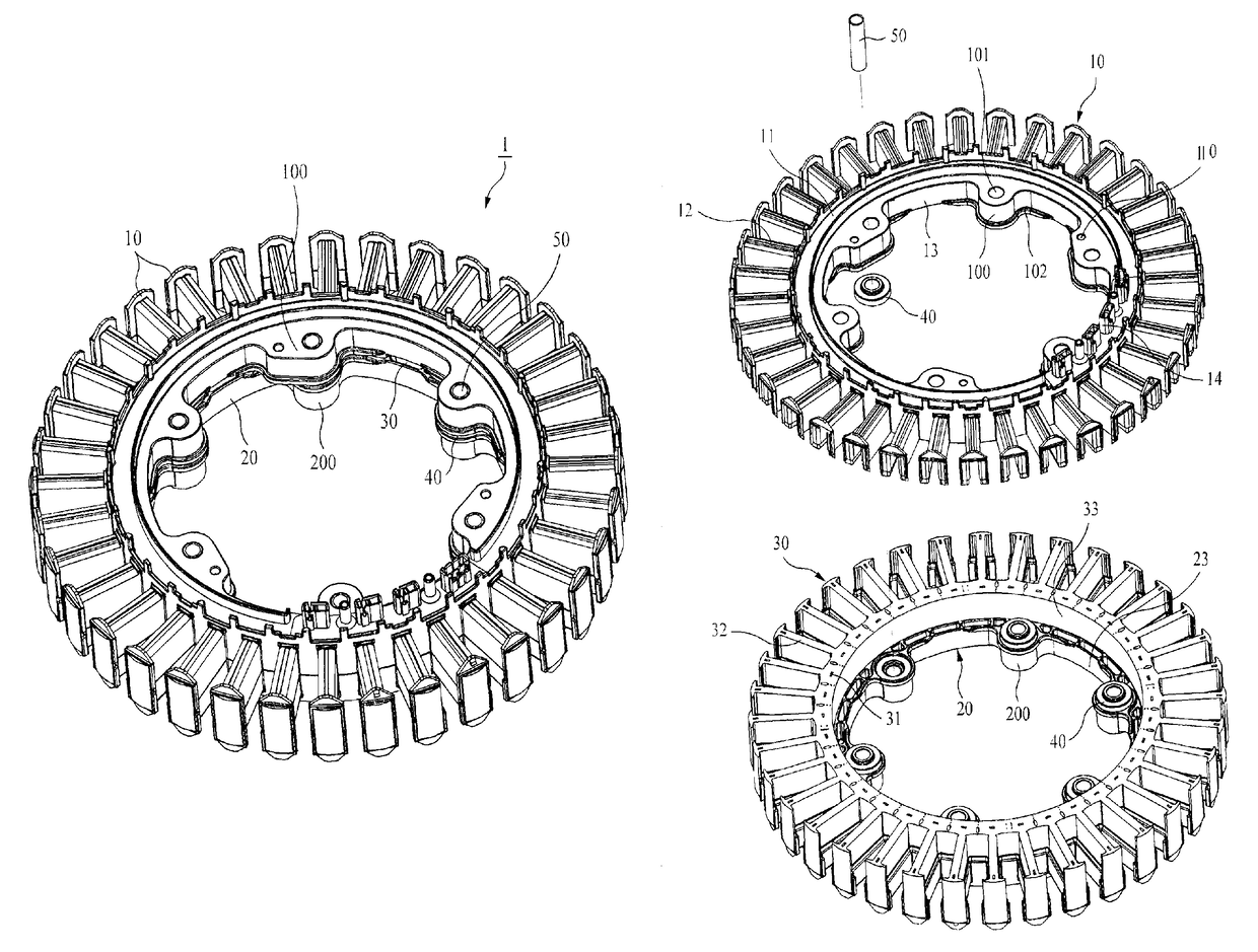
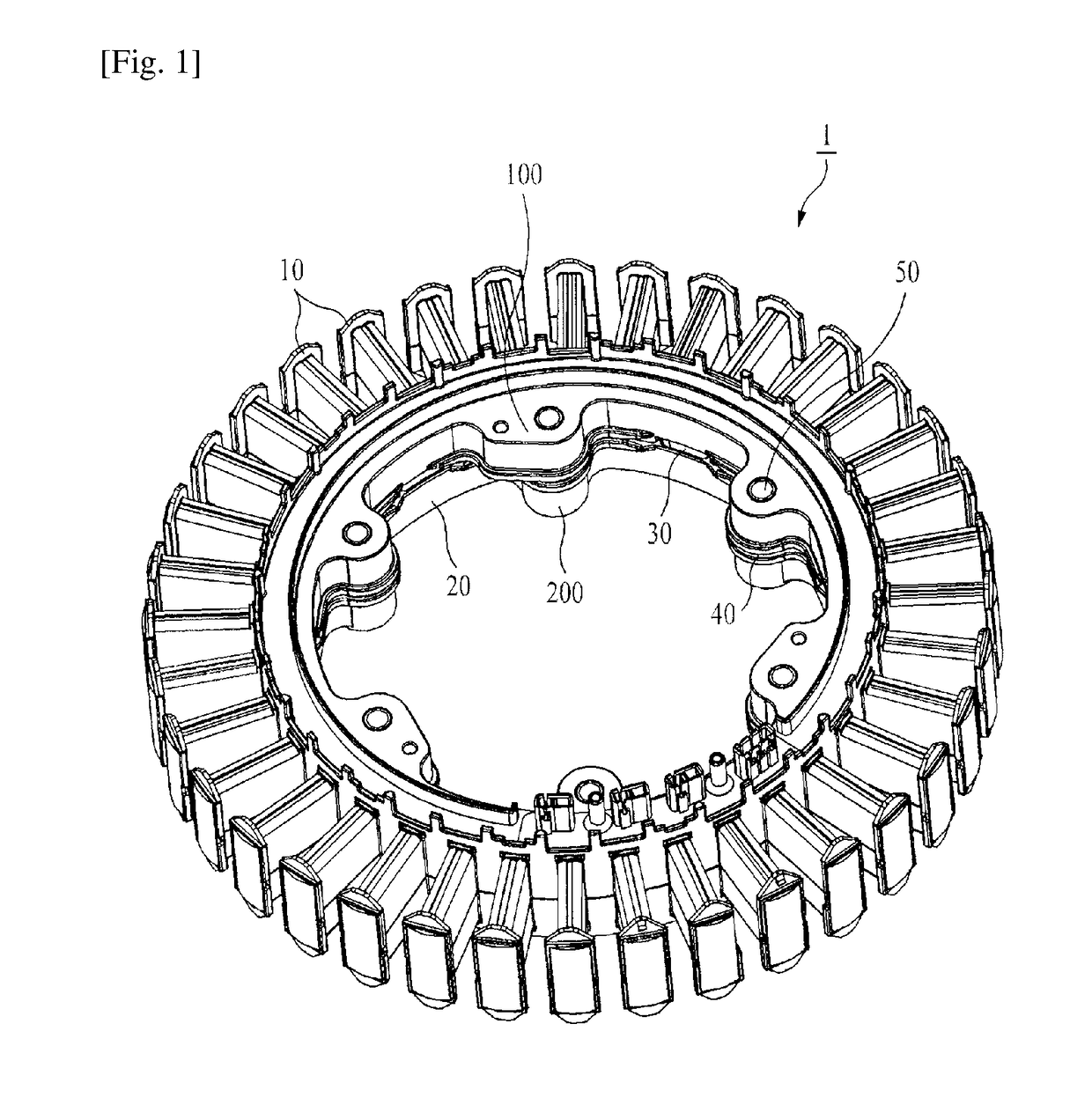
[0022]FIG. 1 is a perspective view showing a stator 1 of a motor for a washing machine according to a preferred embodiment of the present invention.

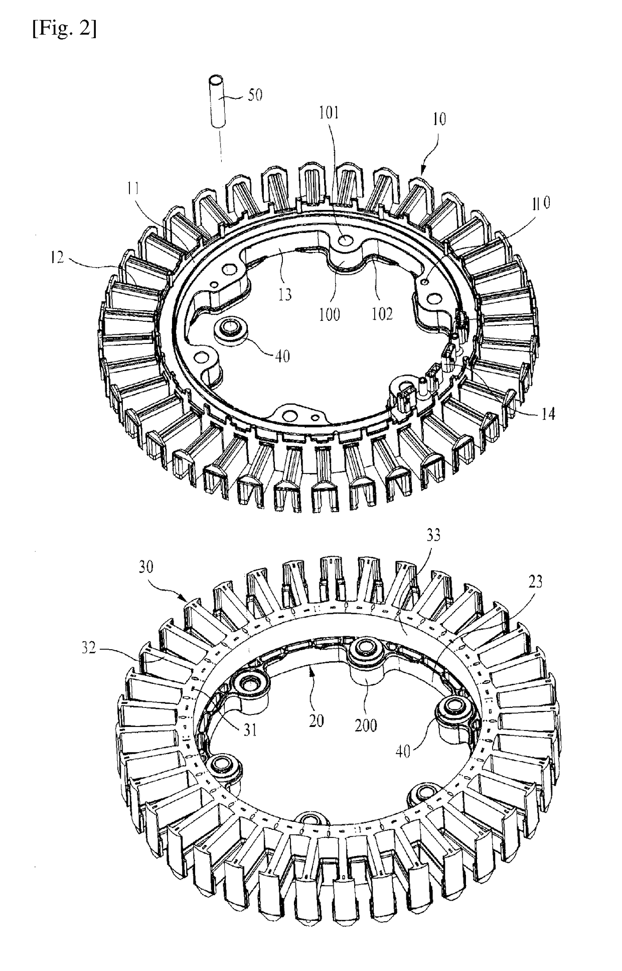
[0023]As shown in FIG. 1, the stator 1 of the motor for the washing machine according to the preferred embodiment of the present invention includes an upper insulator 10, a lower insulator 20 and a stator core 30.

[0024]The stator core 30 is manufactured by a plurality of steel sheets laminated on top of each other, and the upper part and the lower part of the stator core 30 is insulated by the upper insulator 10 and the lower insulator 20. When the upper insulator 10 and the lower insulator 20 are joined to the upper part and the lower part of the stator core 30, the inner circumferential surface of the upper insulator 10 and the inner circumferential surface of the lower insulator 20 do not come into contact with each other but are spaced apart from each other at a predetermined interval. The stator core 30 is exposed through the interv...


PUM


Abstract

Disclosed is a stator of a motor for a washing machine including: a stator core manufactured by a plurality of steel sheets laminated on top of each other, the stator core having a core base and a plurality of teeth radially formed on the core base; an upper insulator which covers the upper parts of the core base and the teeth to insulate them, the upper insulator having least three upper fastening parts which are formed therein and each of which has an upper fastening hole; and a lower insulator which covers the lower parts of the core base and the teeth to insulate them, the upper insulator having least three upper fastening parts which are formed therein and each of which has a lower fastening hole.

Description

CROSS REFERENCE TO PRIOR APPLICATIONS[0001]This application is a National Stage Application of PCT International Patent Application No. PCT / KR2014 / 005285 filed on Jun. 17, 2014, under 35 U.S.C. § 371, which claims priority to Korean Patent Application No. 10-2014-0038576 filed on Apr. 1, 2014, which are all hereby incorporated by reference in their entirety.TECHNICAL FIELD[0002]The present invention relates to a stator of a motor for a washing machine, and more particularly, to a stator of a motor for a washing machine which can prevent noise and vibration while operating and reduce manufacturing costs.BACKGROUND ART[0003]In general, a motor for a washing machine includes a rotor and a stator. The stator includes a stator core in which a number of steel sheets are laminated on top of each other and an insulator surrounding the stator core. Such a structure of the stator is disclosed in U.S. Pat. Nos. 7,336,014 and 7,362,028 and U.S. Patent Publication No. 2011 / 0036127.[0004]In U.S. ...

Claims


Application Information

Patent Timeline
Patent Type & Authority Patents(United States)
IPC IPC(8): H02K5/24H02K1/04H02K1/18H02K1/14H02K7/14
CPCH02K5/24H02K1/04H02K1/187H02K1/146H02K7/14
Inventor JANG, JEONG CHEOLLEE, JI MINYANG, GYEONG SIK
Owner NEW MOTECH
Learn More