Draw-works and method for operating the same

a technology of drawing and working parts, applied in the field of drawing parts, can solve the problems of increasing the cost and weight of the system, reducing the efficiency of the system, so as to achieve the effect of increasing the speed

Active Publication Date: 2018-11-27
GRANT PRIDECO LP
View PDF13 Cites 110 Cited by
  • Summary
  • Abstract
  • Description
  • Claims
  • Application Information

AI Technical Summary

Benefits of technology

[0015]The disclosure, in its broadest form according to the first aspect, solves the challenge with the trade-off between hoisting weight and speed capacity. The elongated hoisting member, which typically will be a wire rope of some sort, may be reeled from one or both of the drums. By disconnecting / unlocking one of the drums from the rotation means, all torque from the rotation means will be available for the other one of the drums. This operation mode may be used when lifting particularly heavy weights, such as casing strings or BOPs, where hoisting speed is not of the essence. By connecting both drums to the rotation means, the available torque will be shared between the two drums, while the line speed, as seen from a travelling block, will be substantially doubled compared to the mode where all torque is available for one drum. This latter mode may be particularly useful in tripping and other operations where speed is of the essence, but where the load is less heavy. As such, a draw-works according to this arrangement may thus provide the advantage of increased speed, as also seen in the dual draw-works according to the prior art, while at the same time offering maximum torque, as typically found in single draw-works while at the same time not having to double the motor capacity. The draw-works according to this arrangement may thus also be regarded as comprising a simple and rather in-expensive 2:1 transmission.
[0016]In one embodiment, the at least one of said first drum and said second drum may be selectively connectable to and disconnectable from said rotation means by means of a remotely operateable connection, such as a remotely operateable spline connection. In alternative embodiments, the connection may be realized in terms other mechanical connections / couplings, such as locking dogs, locking claws, a friction coupling or of a combination of these. The couplings / connections may be remotely operateable. This has the great advantage of the draw-works being able to switch remotely and quickly between the two modes mentioned above, i.e. driving both drums or driving only one drum. The remote operation may be implemented by means of an actuator which may be electric, hydraulic or pneumatic. The switching may be done manually or automatically by means of a control unit. Typically the drums will be suspended around a rotatable shaft by means of a set of bearings. When the connection / coupling is activated / engaged, the drum will rotate with the shaft, whereas when the connection is dis-engaged the shaft may rotate freely inside the drum in the bearings. In one embodiment, a drum which has been disconnected from the rotation means, typically from the shaft as described above, may be locked to supporting structure of the drum, typically to a drum housing / draw-works skid frame, to ensure that it does not rotate with the shaft. The locking may be done by means of a draw-works braking means, which may be implemented as conventional disc brakes or band brakes as will be understood by a person skilled in the art.
[0018]Said first rotation means may comprise one or more motors, gears and a first rotatable shaft, and said second rotation means may comprise one or more motors, gears and a second rotatable shaft, and wherein said first rotatable shaft may be selectively, mechanically connectable to and disconnectable from said second rotatable shaft. Typically each rotation means will comprise a plurality of AC motors rotating a shaft via a gearing means. By allowing the shaft of the rotation means to be split into two, i.e. to disconnect / unlock the first shaft from the second shaft, the two drums, each having one or more motors, may be operated independently, which may be beneficial for redundancy and / or for line exchange operations. The first and second shafts may subsequently be connected again to run the shaft as one with the combined torque from the motors from both sides. In one embodiment, said first rotatable shaft may be selectively, mechanically connectable to and disconnectable from said second rotatable shaft by means of a remotely operateable connection, such as a remotely operateable spline connection. In other embodiments, the connection may be realized in terms of other mechanical connections, such as locking dogs, locking claws, a friction coupling or a of combination of these, all preferably remotely operateable. The remote operation may be implemented by means of actuator which may be electric, hydraulic or pneumatic. As described above for the drum's connection to and disconnection from the shaft / rotation means, the remote operation may allow for a quick switch between various modes of operation of the draw-works described herein. When the first and second shafts are disconnected, the two drums may be operated independently, as with the dual draw-works according to the prior art.

Problems solved by technology

Dual draw-works has the disadvantage of leaving a large footprint as a draw-works is placed on each side of the derrick, the available space often being limited on rig floors.
This problem could be solved by doubling the motor capacity on one or both of the draw-works in a conventional dual draw-works system, but that would significantly increase the cost and weight of the system which already leaves a very large footprint.

Method used


Image

  • Draw-works and method for operating the same
  • Draw-works and method for operating the same
  • Draw-works and method for operating the same

Examples


Embodiment Construction

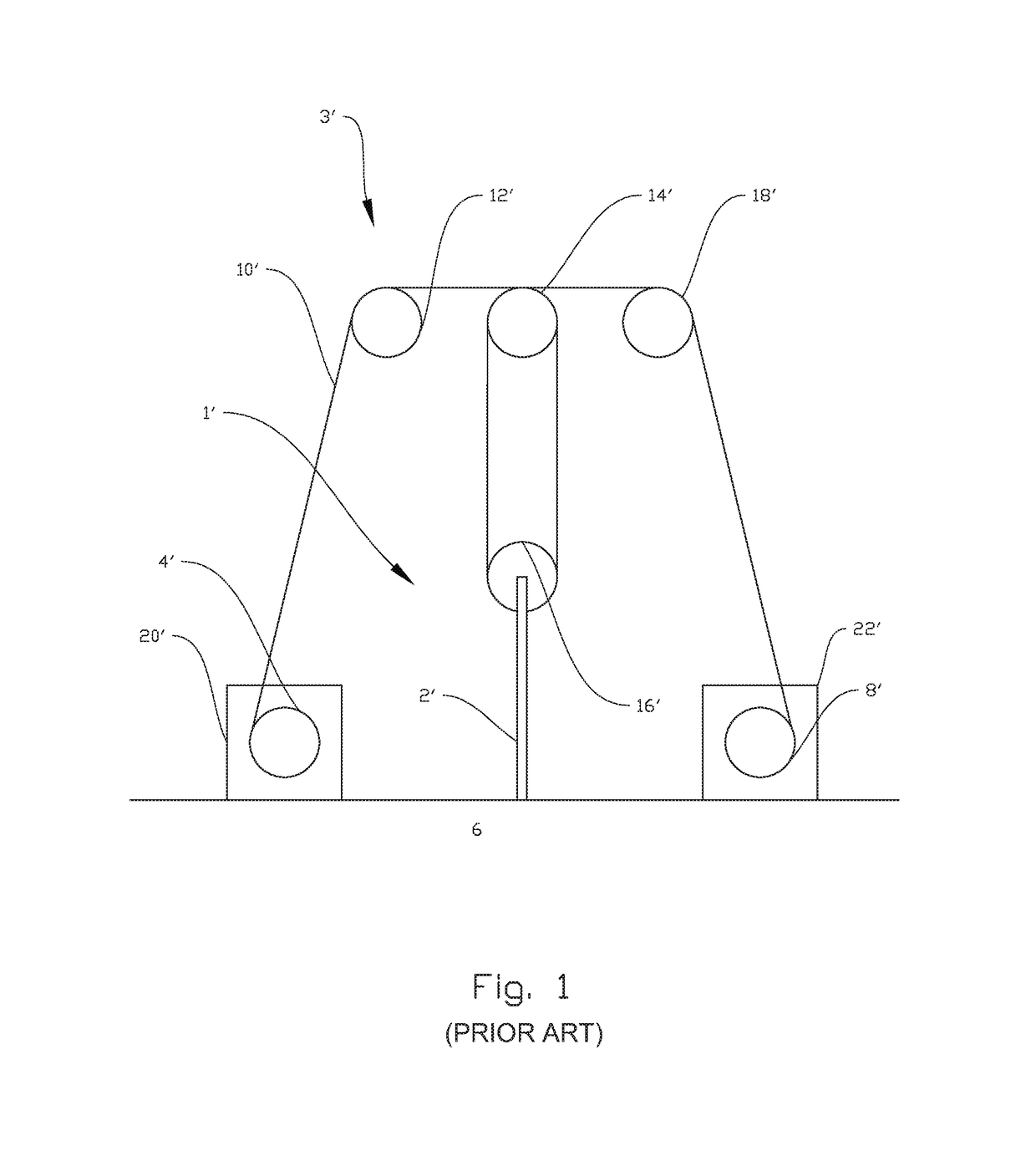
[0034]In the following, the reference numeral 1 will indicate a draw-works according to the present disclosure, whereas the reference numeral 1′ indicates a draw-works according to the prior art. Identical reference numerals will indicate identical or similar features in the drawings. The figures are shown schematically and simplified and various features in the figures are not necessarily drawn to scale.

[0035]FIG. 1 shows a prior art hoisting system 3′ with a dual draw-works 1′ according to the prior art. An elongated hoisting member 10′ in the form of a wire rope is stored and reeled from a first drum 4′ placed on the left hand side of a derrick 6′ and a second drum 8′ placed on the right hand side of the derrick 6′. The wire rope 10′, is reeled from the first drum 4′ to the second drum 8′, over a first guiding sheave 12′ to a crown block 14′ down to a travelling block 16′, where the wire rope 10′ makes several turns about the crown block 14′ and travelling block 16′ to generate t...


PUM


Abstract

Disclosed is a draw-works and a method of operation. The draw-works includes a first drum configured to store and reel in an elongated hoisting member, such as a hoisting cable, a second drum configured to store and reel in the elongated hoisting member, and a rotation device configured to rotate the first and second drums, wherein at least one of the drums is selectively connectable to and disconnectable from the rotation device.

Description

CROSS-REFERENCE TO RELATED APPLICATIONS[0001]This application claims priority to European Patent Application No. 15161583.8 having the International Filing date of Mar. 30, 2015 and entitled “Draw-Works and Method for Operating the Same,” which is hereby incorporated herein by reference in its entirety for all purposes.STATEMENT REGARDING FEDERALLY SPONSORED RESEARCH OR DEVELOPMENT[0002]Not applicableBACKGROUND[0003]The present disclosure relates to a draw-works. More specifically the disclosure relates to a draw-works comprising a first drum for storing and reeling an elongated hoisting member, a second drum for storing and reeling the elongated hoisting member and a rotation means for rotating the first and second drums. The disclosure also relates to a method for operating a draw-works.[0004]A draw-works is the primary hoisting machinery that is a component of a drilling rig. Its main function is to provide a means of raising and lowering the travelling blocks, the travelling blo...

Claims


Application Information

Patent Timeline
Patent Type & Authority Patents(United States)
IPC IPC(8): B66D1/26E21B19/084E21B19/00B66D1/14
CPCB66D1/26E21B19/084E21B19/008B66D1/14
Inventor SORENSEN, RUNEWATSON, TIMOTHYRAJIC, IVAN
Owner GRANT PRIDECO LP
Why Eureka
Try Eureka