
Optical cable for terrestrial networks

a technology of optical cables and terrestrial networks, applied in the field of optical cables, can solve the problems of reducing the mechanical stability of the sheath, increasing the thickness of the jacket, and so as to achieve the effect of preserving the integrity of the jacket, reducing the risk of injuries, and easy removal

Active Publication Date: 2018-11-27
PRYSMIAN SPA
View PDF14 Cites 0 Cited by
  • Summary
  • Abstract
  • Description
  • Claims
  • Application Information

AI Technical Summary

Benefits of technology

Enables safe and easy removal of long sheath portions with minimal risk of injury, maintaining mechanical stability and allowing increased fiber count without the need for grooves or hazardous tools.

Problems solved by technology

First of all, the grooves basically are thinner sheath areas, which reduce mechanical stability of the sheath for easing its buckling as the cable is bent for the purpose of removing the jacket. However, it is undesirable that the jacket buckles whenever the cable is bent or twisted for purposes other then jacket removal, e.g. for coiling the cable on a drum or laying it down along a narrow curved path (which is very common during installation of FTTH or FTTP networks). Using grooves as disclosed by US 2012 / 0063731 therefore disadvantageously results in a trade-off between easiness of jacket removal and jacket mechanical performance (in particular, bending and torsion performance).
However, since the external diameter of cables for FTTH or FTTP applications is subject to narrow constraints (because spaces available for installation of cables in such applications are typically very narrow and because the external size of the cables shall be compatible with the size of other components such as connectors, clips, etc.), an increase of the jacket thickness may be achieved only by decreasing the internal diameter of the jacket.
This however disadvantageously implies a reduction of the space available for the optical core within the cable, which in turn implies a reduction of the maximum cable fiber count (namely, the maximum number of optical fiber units which may be arranged in the cable).

Method used


Image

  • Optical cable for terrestrial networks
  • Optical cable for terrestrial networks
  • Optical cable for terrestrial networks

Examples


second embodiment

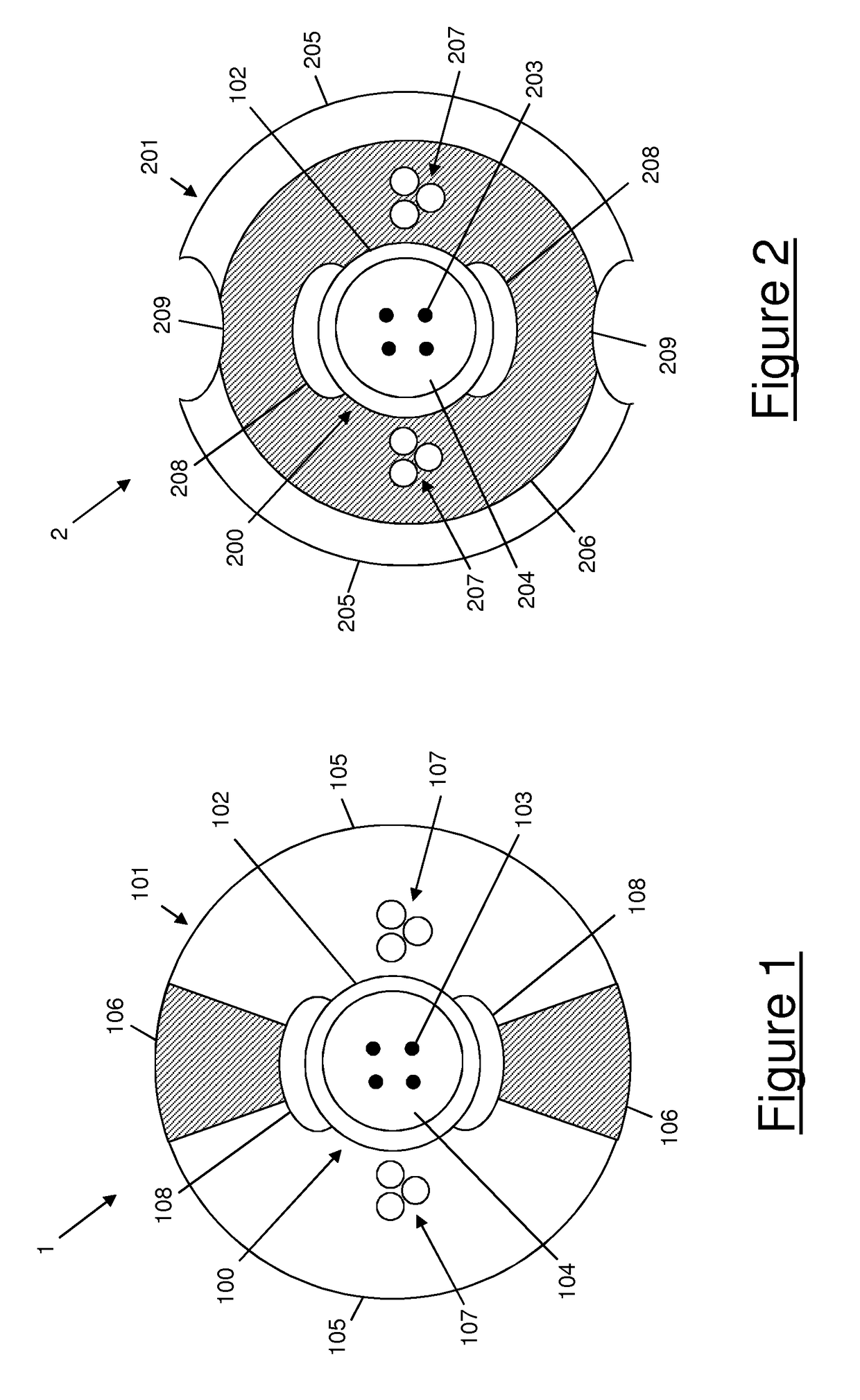
[0075]FIG. 2 shows an optical cable 2 according to the present invention.

[0076]The optical cable 2 according to the second embodiment of the present invention is a drop cable for FTTH or FTTP applications.

[0077]The optical cable 2 comprises an optical core 200 and a sheath 201 surrounding the optical core 200.

[0078]The optical core 200 comprises a buffer tube 202 and a number of optical fibers 203. The features of the optical core 200 and its components are similar to that of the optical core 100 shown in FIG. 1. Therefore, a detailed description will not be repeated.

[0079]According to the second embodiment, the sheath 201 comprises a first longitudinally extending portion 205 made of a first, higher fracture toughness material and a second longitudinally extending portion 206 made of a second, lower fracture toughness material.

[0080]The first portion 205 and the second portion 206 have annular, concentric cross-sections.

[0081]The first portion 205 is arranged in an outermost positi...

first embodiment

[0085]The features of the first, higher fracture toughness material and second, lower fracture toughness material are preferably the same as discussed above with reference to the Therefore, a detailed description will not be repeated. The sheath 201 is preferably extruded by an extrusion equipment comprising an extrusion die modified with a double groove allowing co-extrusion of both the annular portions 205, 206 of the sheath 201.

[0086]The cable 2 also preferably comprises two strength members 207 arranged within the thickness of the sheath 201. In particular, the two strength members 207 are arranged at diametrically opposed positions, embedded within the thickness of the second annular portion 206. Preferably, each strength member 207 comprises a number of (three, in the embodiment of FIG. 2) metallic strands, e.g. coated steel strands. The strength members 207 are preferably arranged on a longitudinal plane perpendicular to the longitudinal plane containing the bisector of the ...

fourth embodiment

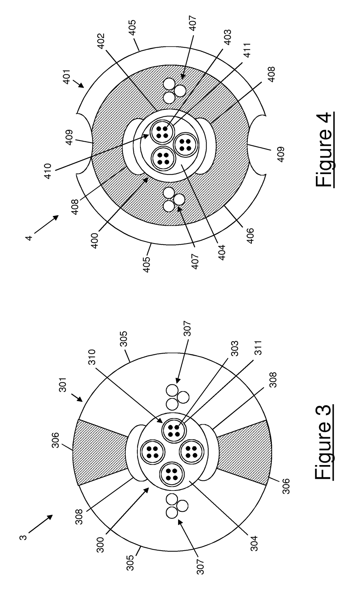
[0114]This fourth embodiment then exhibits the same advantages as the second one: the sheath may be removed in a very easy and very safe way, and the cable sheath exhibits a particularly high resistance to bending and a particularly reduced risk of splitting at the joints.

[0115]The sheath structure depicted in FIGS. 1 and 3, as well as the sheath structure depicted in FIGS. 2 and 4, may be applied not only to drop cables, but also to other types of terrestrial optical cables, independently of the construction of their optical core.

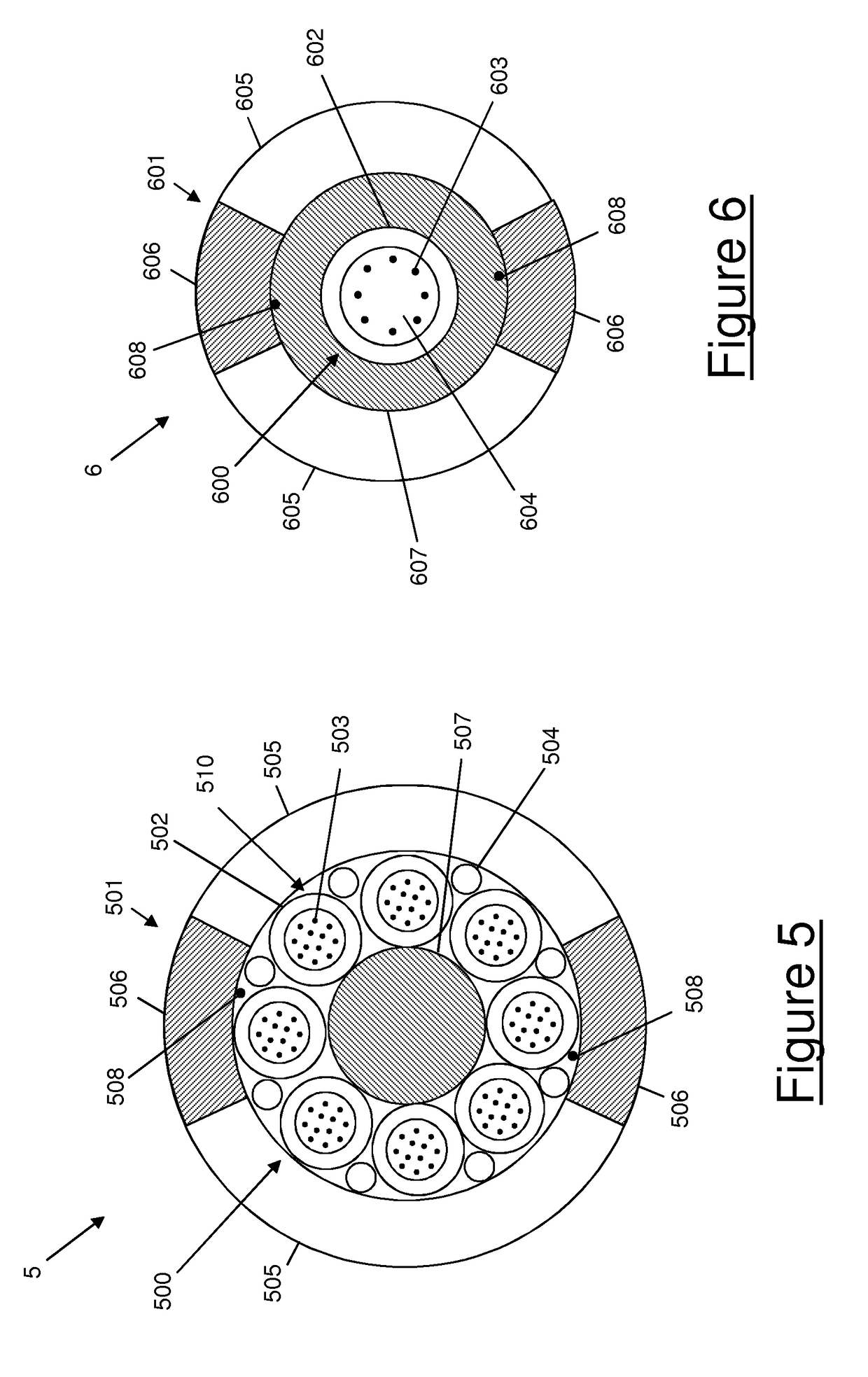
[0116]For instance, FIG. 5 shows an optical cable 5 according to a fifth embodiment of the present invention. The optical cable 5 according to the fifth embodiment of the present invention is a multi-loose tube cable for terrestrial networks.

[0117]The optical cable 5 comprises an optical core 500 and a sheath 501 surrounding the optical core 500.

[0118]The optical core 500 comprises eight optical units 510, each optical unit 510 comprising a respective buff...


PUM


Abstract

An optical cable includes an optical core and an external sheath surrounding the optical core. The external sheath includes a first material having a first, higher fracture toughness and a second material having a second, lower fracture toughness. The first and second materials are arranged so that the second, lower fracture toughness material is accessible from outside the cable along at least one longitudinally extending area of the sheath outer surface. For accessing the optical core of the cable, a short longitudinal cut, namely, few centimeters, is made with a blade in the accessible second, lower fracture toughness material. Then, its cut edges are pulled apart by hand. The pulling force causes the lower fracture toughness material to fracture, thereby propagating the initial short cut longitudinally along the sheath through its whole thickness.

Description

CROSS REFERENCE TO RELATED APPLICATION[0001]This application is a national phase application based on PCT / EP2013 / 065931, filed Jul. 29, 2013, the content of which is incorporated herein by reference.TECHNICAL FIELD[0002]The present invention relates to the field of optical cables. More particularly, the present invention relates to an optical cable for terrestrial networks, in particular—but not exclusively—optical access networks such as FTTH (Fiber To The Home) networks and FTTP (Fiber To The Premises) networks.BACKGROUND ART[0003]As known, an optical cable typically comprises an optical core including one or more optical fibers and an external sheath enclosing the optical core. The external sheath is typically made of a polymeric material and has the primary function of protecting the optical core from the mechanical point of view.[0004]Within the external sheath, the optical fibers may be arranged in various ways. In particular, in the so-called “loose tube cables”, the optical ...

Claims


Application Information

Patent Timeline
Patent Type & Authority Patents(United States)
IPC IPC(8): G02B6/44
CPCG02B6/443G02B6/4495G02B6/4475G02B6/4427G02B6/4431
Inventor LANG, IAN DEWIROBERTS, PAUL JOHNDAVIES, MARTIN VINCENTSUTEHALL, RALPH
Owner PRYSMIAN SPA
Learn More