Magnetic light emitting diode (LED) lighting system

a technology of led lighting and light-emitting diodes, which is applied in the direction of lighting and heating apparatus, semiconductor devices for light sources, lighting support devices, etc., can solve the problems of undesirable weight and/or size, add to the weight and/or size of led systems, etc., to achieve desirable size and weight, bright working environment in small working spaces, and maintain effective heat dissipation

Active Publication Date: 2018-12-04
LUX LIGHTING SYST
View PDF75 Cites 4 Cited by
  • Summary
  • Abstract
  • Description
  • Claims
  • Application Information

AI Technical Summary

Benefits of technology

[0004]The system of the present disclosure provides a mountable LED lighting apparatus that uses LEDs (e.g., relatively high-output LEDs) sufficient for illumination. The present disclosure provides such a lighting apparatus that allows a single element, such as a magnet, to provide mounting and heat-sink functions. Such a lighting apparatus may allow the use of one or more relatively high-output LEDs while maintaining effective heat dissipation and a desirable size and weight.
[0005]The mountable LED lighting apparatus described in the present disclosure may allow high-output LEDs to be used in a variety of applications. For example, the lighting apparatus may be mounted on an industrial machine, such as a mill or lathe, to provide a bright working environment in small working spaces, obviating the need for separate lights or large lights that may interfere with the machinist. Alternatively, the lighting apparatus may be mounted on various parts of an automobile, such as the wheel wells, a truck bed, or the underside of the chassis, to provide bright, LED-generated light effects on or around the automobile. In each of these exemplary applications, a small form factor is desirable, so a lighting apparatus that combines the heat-sink and mounting functions into a single element, such as a magnet, is desirable.

Problems solved by technology

Incorporating an extra element, such as an external heat sink, however, can add to the weight and / or size of the LED system.
In some applications, this added weight and / or size can be undesirable.

Method used


Image

  • Magnetic light emitting diode (LED) lighting system
  • Magnetic light emitting diode (LED) lighting system
  • Magnetic light emitting diode (LED) lighting system

Examples


Embodiment Construction

[0019]In the following detailed description, reference is made to the accompanying drawings, which form a part hereof. In the drawings, similar symbols typically identify similar components, unless context dictates otherwise. The illustrative embodiments described in the detailed description, drawings, and potential points of novelty are not meant to be limiting. Other embodiments may be utilized, and other changes may be made, without departing from the spirit or scope of the subject matter presented here. It will be readily understood that the aspects of the present disclosure, as generally described herein, and illustrated in the Figures, may be arranged, substituted, combined, and designed in a wide variety of different configurations, all of which are explicitly contemplated and make part of this disclosure.

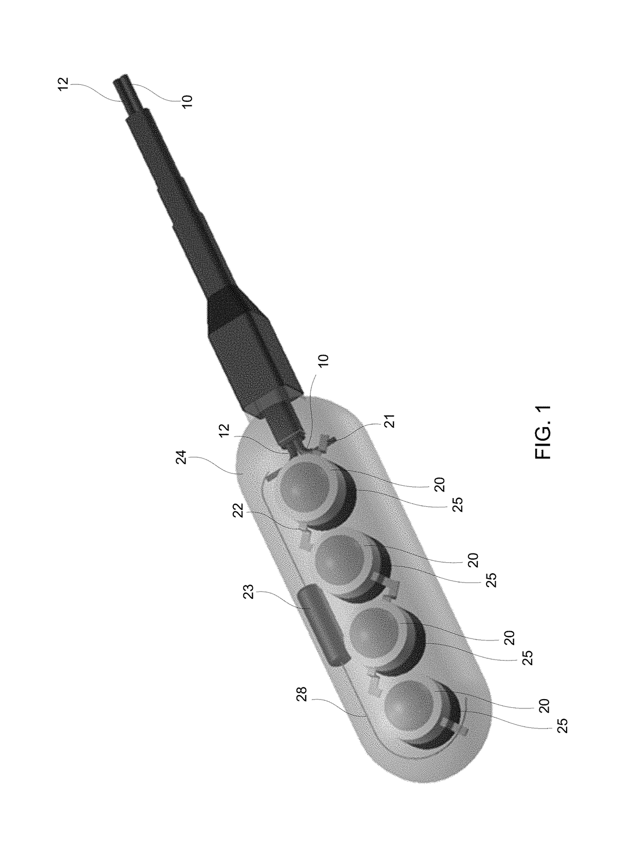
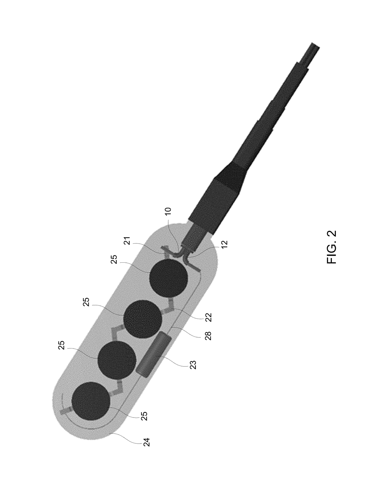
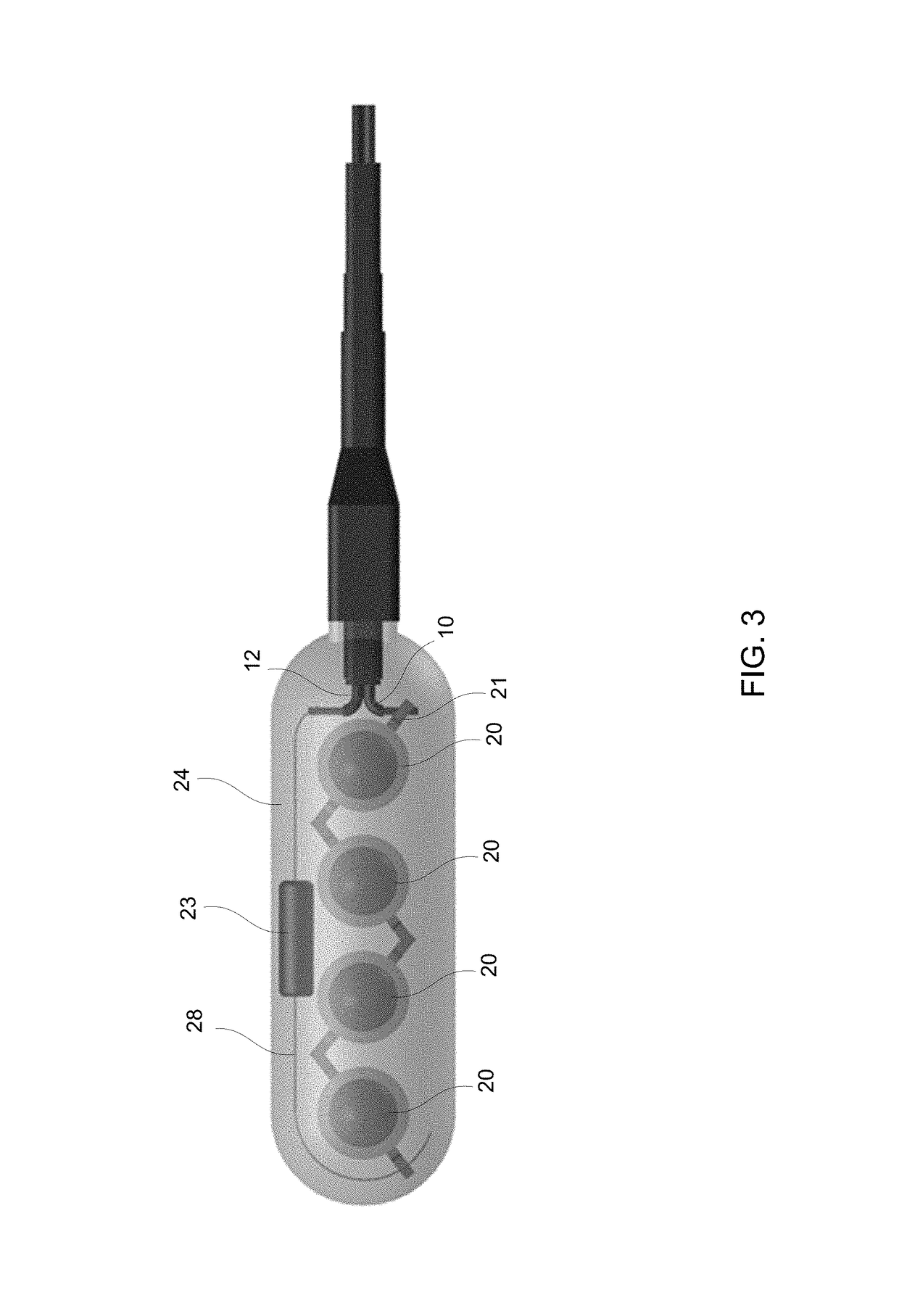
[0020]This disclosure is generally drawn to methods, systems, devices and / or apparatus related to light emitting diode (LED) lighting systems for various applications. Speci...


PUM


Abstract

The present disclosure describes example magnetic LED lighting systems. A lighting apparatus in accordance with the present disclosure may include LEDs connected in series with a resistor. The LEDs are each coupled, directly or via thermal vias through a mounting element, to one or more magnets. The magnets may serve dual purposes: as a heat sink to dissipate heat and enable LEDs to be used, and as a mounting device to mount the lighting apparatus to a desirable location, such as on an automobile or an industrial machine. The dual-purpose magnets may eliminate the need for an additional heat sink element, thereby reducing weight and / or size of the lighting apparatus.

Description

CROSS-REFERENCE TO RELATED APPLICATIONS[0001]This application claims priority to U.S. Provisional Application No. 62 / 138,766, which was filed on Mar. 26, 2015, the entirety of which is hereby incorporated by reference.BACKGROUND[0002]Lighting systems incorporating light-emitting diodes (“LEDs”) are increasingly popular. LEDs present certain advantages over conventional incandescent and fluorescent lights, including compactness, longevity, and durability. An LED emits light when the p-n junction comprising the diode is forward-biased, enabling a current to flow across the junction and emit light in the process. LEDs are available in a wide variety of colors, including red, orange, yellow, green, blue, and white. LEDs are being incorporated into products at an increasing rate. For example, some manufacturers make lightbulbs for conventional fixtures using LEDs. LEDs made from polymers (e.g., organic LEDs) are being incorporated into displays. LEDs come in many shapes and sizes, from s...

Claims


Application Information

Patent Timeline
Patent Type & Authority Patents(United States)
IPC IPC(8): B60Q1/26F21V19/00F21S45/47F21V21/096F21V29/70F21S43/19F21S43/14F21Y103/10F21Y115/10
CPCF21V29/70B60Q1/2615B60Q1/2696F21S43/14F21V19/002F21V21/096F21S43/19F21Y2115/10F21S45/47F21Y2103/10
Inventor FAY, JONATHAN ERIC
Owner LUX LIGHTING SYST
Why Eureka
Try Eureka