Multiphase power supply and failure mode protection

a multi-phase power supply and failure mode technology, applied in the field of multi-phase power supplies, can solve the problems of unsatisfactory output of 48 vdc instead of 1 vdc, severe damage to any circuitry powered, and serious damage to respective powered devices

Active Publication Date: 2018-12-11
INFINEON TECH AUSTRIA AG
View PDF7 Cites 0 Cited by
  • Summary
  • Abstract
  • Description
  • Claims
  • Application Information

AI Technical Summary

Benefits of technology

[0007]Embodiments herein include novel ways of preventing a respective power supply from damaging a load due to a failure of a respective power supply phase.
[0008]More specifically, embodiments herein include a multi-phase power supply circuit that converts a received input voltage into a respective output voltage to power a load. A first power supply phase of the multi-phase power supply includes a core power supply circuit including, for example, high side switch circuitry and low side switch circuitry. During normal operation, the core power supply circuit (such as a combination of the high side switch circuitry and the low side switch circuitry of a buck converter) receives and converts an input voltage into a respective output voltage to power a load. To provide failure mode protection with respect to the core power supply circuit and prevent a failure mode of producing a dangerous over-voltage condition, the first power supply phase includes an input voltage switch circuit disposed between an input voltage source and the high side switch circuitry in the first phase. During operation, the input voltage switch circuit provides a way of selectively isolating the input voltage received from the voltage source from the high side switch circuitry.

Problems solved by technology

This conventional single stage power supply is prone to a failure condition in which respective high side switch circuitry in the phase is stuck (fails) to an ON state, potentially causing the input voltage of 48 V DC to become the output voltage instead of a down-converted output of 1 VDC.
This failure condition of outputting 48 VDC instead of 1 VDC is undesirable because inadvertently outputting such a high output voltage (such as 48 VDC) during the failure condition will likely cause severe damage to any circuitry powered by the respective power converter system.
Inadvertently outputting 12 V DC (albeit much less than 48 V DC in the above failure case for a single stage converter) during a failure condition from an output port that should output only output 1 VDC may also cause serious damage to respective powered devices.
Moreover, in addition to being prone to failure as discussed above, another disadvantage of this two-stage power converter circuit is that the power supply circuit is potentially twice the size of a single stage converter because it includes two converters.

Method used


Image

  • Multiphase power supply and failure mode protection
  • Multiphase power supply and failure mode protection
  • Multiphase power supply and failure mode protection

Examples


Embodiment Construction

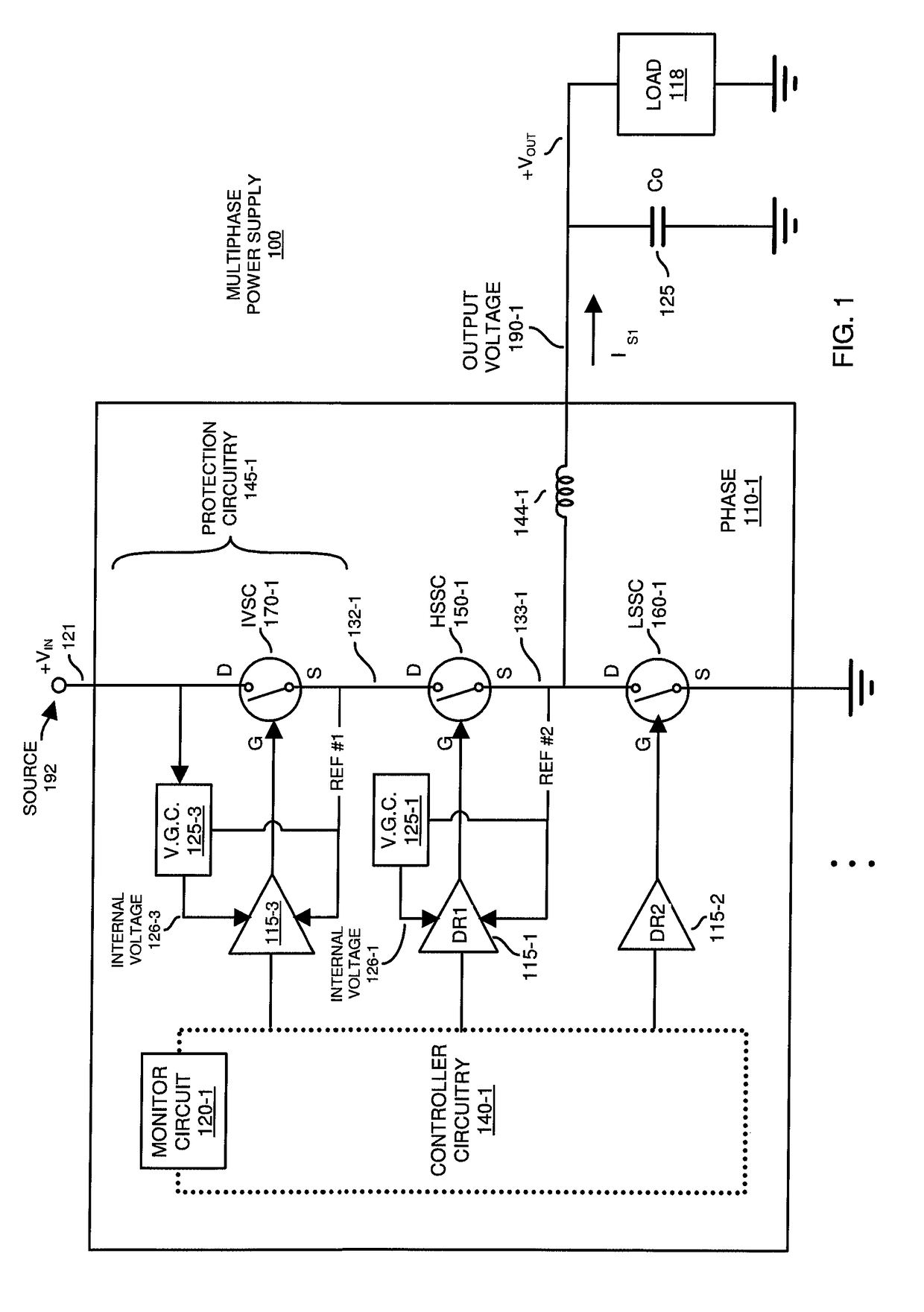
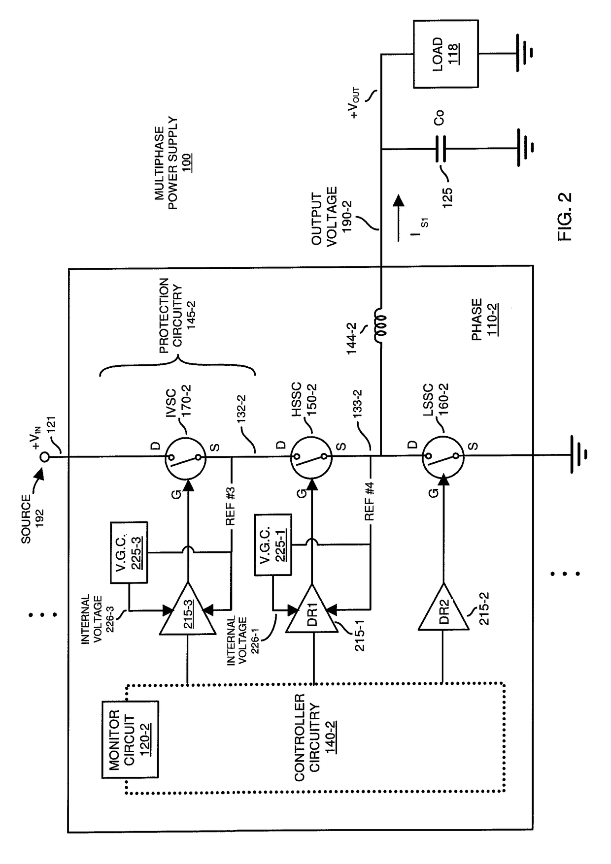
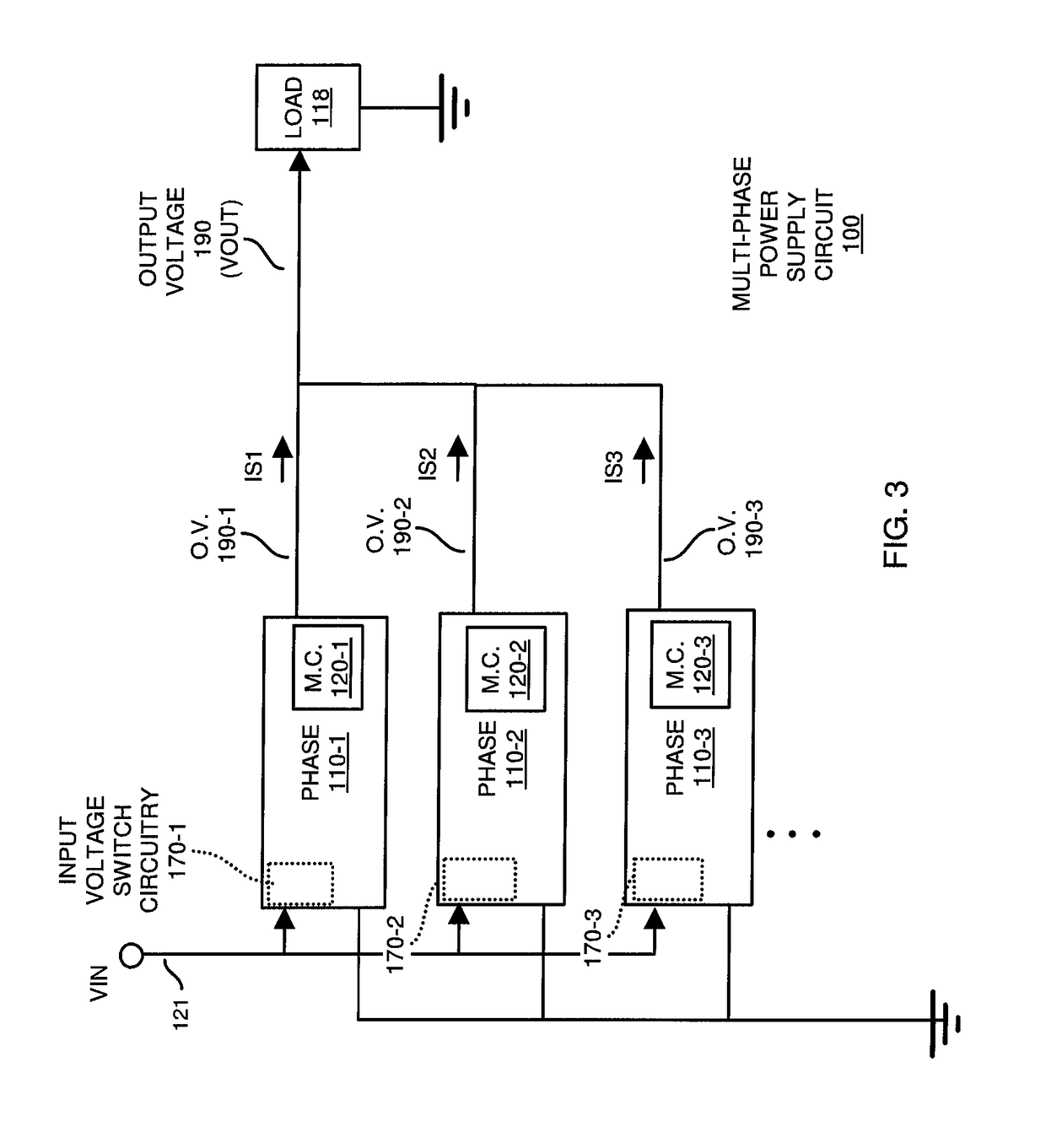
[0042]In accordance with embodiments herein, a multi-phase power supply circuit includes multiple phases to convert an input voltage into a respective output voltage to power a load. A first phase of the multi-phase power supply includes a core power supply circuit such as or including a buck converter. During normal operation, the core power supply circuit converts an input voltage into a respective output voltage to power a load. To provide failure mode protection with respect to the core power supply circuit and prevent a failure mode in which the first phase would otherwise produce and output a dangerous over-voltage, the first power supply phase includes an input voltage switch circuit disposed between an input voltage source and the core power supply circuit. The input voltage switch circuit provides a way of isolating the input voltage received from the voltage source from being delivered to the core power supply circuit during a failure mode. As a specific example, in respon...


PUM


Abstract

A multi-phase power supply circuit includes multiple phases to convert an input voltage into a respective output voltage to power a load. A first phase of the multi-phase power supply includes a core power supply circuit including, for example, high side switch circuitry and low side switch circuitry. During normal operation, the core power supply circuit converts an input voltage into a respective output voltage to power a load. To provide failure mode protection with respect to the core power supply circuit and prevent a failure mode in which the first phase would otherwise produce a dangerous over-voltage condition, the first power supply phase includes an input voltage switch circuit disposed between an input voltage source and the core power supply circuit. The input voltage switch circuit provides a way of preventing the input voltage from being conveyed to the core power supply circuit during a failure mode.

Description

BACKGROUND[0001]Conventional multi-phase power supplies may include one or more DC to DC converters to produce a respective output voltage to power a load. Any number of phases in a multi-phase power supply can be operated in parallel to produce the output voltage powering the load.[0002]One type of DC to DC converter is a single-stage power converter system. As its name suggests, in the single-stage power converter system, each phase includes a single power converter to convert an input voltage such as 48 V DC (Volts Direct Current) into a respective target output voltage such as 1 volt DC to power a load.[0003]Another type of DC to DC converter is a so-called two-stage power converter system. As its name suggests, the two-stage power converter system includes two power converter stages to produce a respective output voltage. As an example, a first power converter stage typically converts an input voltage such as 48 V DC into an intermediary voltage such as 12 V DC. A second power ...

Claims


Application Information

Patent Timeline
Patent Type & Authority Patents(United States)
IPC IPC(8): H02H3/08H02M3/158H02M1/084H02M1/32H02M1/00
CPCH02M3/158H02M1/084H02M1/32H02M2001/325H02M2001/0009H02H7/1213H02M3/156H02M1/0009H02M1/325
Inventor KHATIB, MUDASSARCLAVETTE, DANNY
Owner INFINEON TECH AUSTRIA AG
Why Eureka
Try Eureka