Electronic protection component

a technology of electronic protection and components, applied in the direction of resistors, emergency protective arrangement details, varistors, etc., can solve the problems of slow response rate of overheating protection, varistor effectiveness loss, performance degradation, etc., and achieve the effect of convenient installation and faster heat transfer speed

Active Publication Date: 2014-09-25
XIAMEN SET ELECTRONICS
View PDF6 Cites 5 Cited by
  • Summary
  • Abstract
  • Description
  • Claims
  • Application Information

AI Technical Summary

Benefits of technology

[0030]In the present invention, the varistor and the thermal fuse are integrated so that the speed of heat transfer is faster and the installation is convenient when in use. Under the action of the melting promoting agent, the melted alloy of the thermal fuse shrinks rapidly toward the two leads and agglomerates to form two b

Problems solved by technology

However, the frequent operation will inevitably cause the performance degradation of a conventional varistor, even cause the varistor to lose its effectiveness.
Therefore, when the conventional varistor suffers transient over-voltage, it will rapidly get partial breakdown therefore potentially cause fire.
The conventional varistor with thermal protection has the following disadvantages: firstly, the conventional varistor with thermal protection has a complex structure s

Method used


Image

  • Electronic protection component
  • Electronic protection component
  • Electronic protection component

Examples


embodiment 1

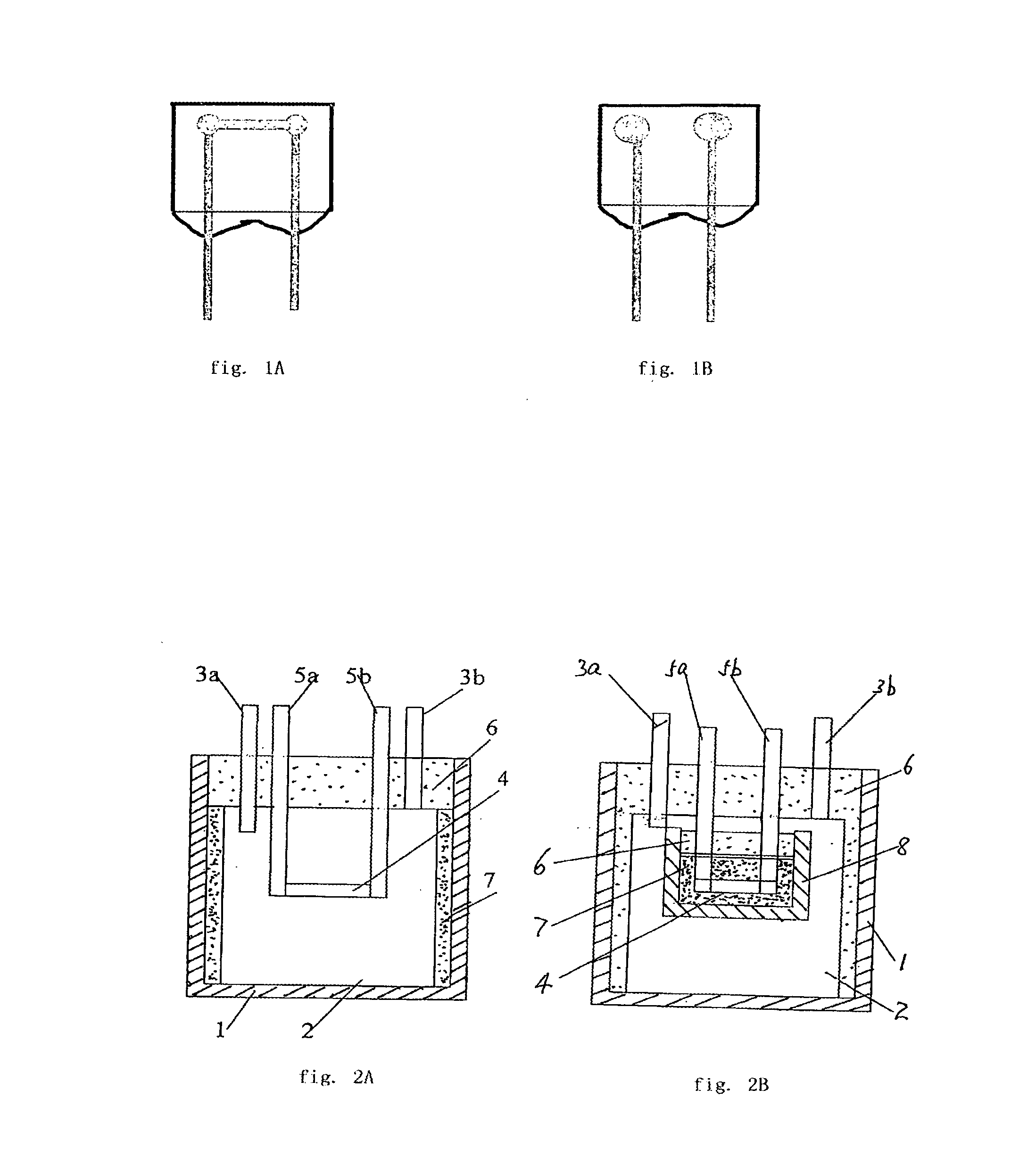
[0052]Shown in FIG. 2A is the drawing of the basic structure of the first embodiment which comprises outer case 1, varistor 2 and alloy-type thermal fuse 4. Varistor 2 and alloy-type thermal fuse 4 are placed in outer case 1 with the surface of varistor 2 being attached to the surface of alloy-type thermal fuse 4. Outer case 1 is filled with alloy melting promoting agent 7. The opening of outer case 1 is sealed with epoxy resin 6 to form a closed cavity. Leads 3 of varistor 2 and leads 5 of thermal fuse 4 are extended to the outside of outer case 1.

[0053]When the electronic protection component is in use, when varistor 2 is heated by various causes, the heat is transferred firstly to the surrounding alloy melting promoting agent 7 from the surface of varistor 2 and then is transferred from melting promoting agent 7 to alloy-type thermal fuse 4 until the alloy is melted due to the heat and balls-up and shrinks towards two leads 5a and 5b of thermalfuse 4 rapidly under the influence o...

embodiment 2

[0054]Shown in FIG. 2B, is the base structure of the second embodiment which comprises varistor 2, alloy-type thermal fuse 4, outer case 1 and inner case 8. Alloy-type thermal fuse 4 and melting promoting agent, e.g. resin 7 are placed in inner case 8 which is made of ceramic or other material of high heat conduction and high electrical insulation, the opening of inner case 8 is sealed with epoxy resin 6, and the inner surface of the inner case 8 is attached to one surface of varistor 2. Then inner case 8 and varistor 2 are placed in outer case 1 with the opening of outer case 1 being sealed with epoxy resin 6 to form a closed cavity.

[0055]When varistor 2 is heated by various causes, heat is directly transferred from the surface of varistor 2 to inner case 8, and then the heat is immediately transferred to alloy-type thermal fuse 4 until the alloy is melted after heating, and thereby the melted alloy shrinks rapidly toward two leads 5a and 5b of thermal fuse 4 under the influence of...

embodiment 3

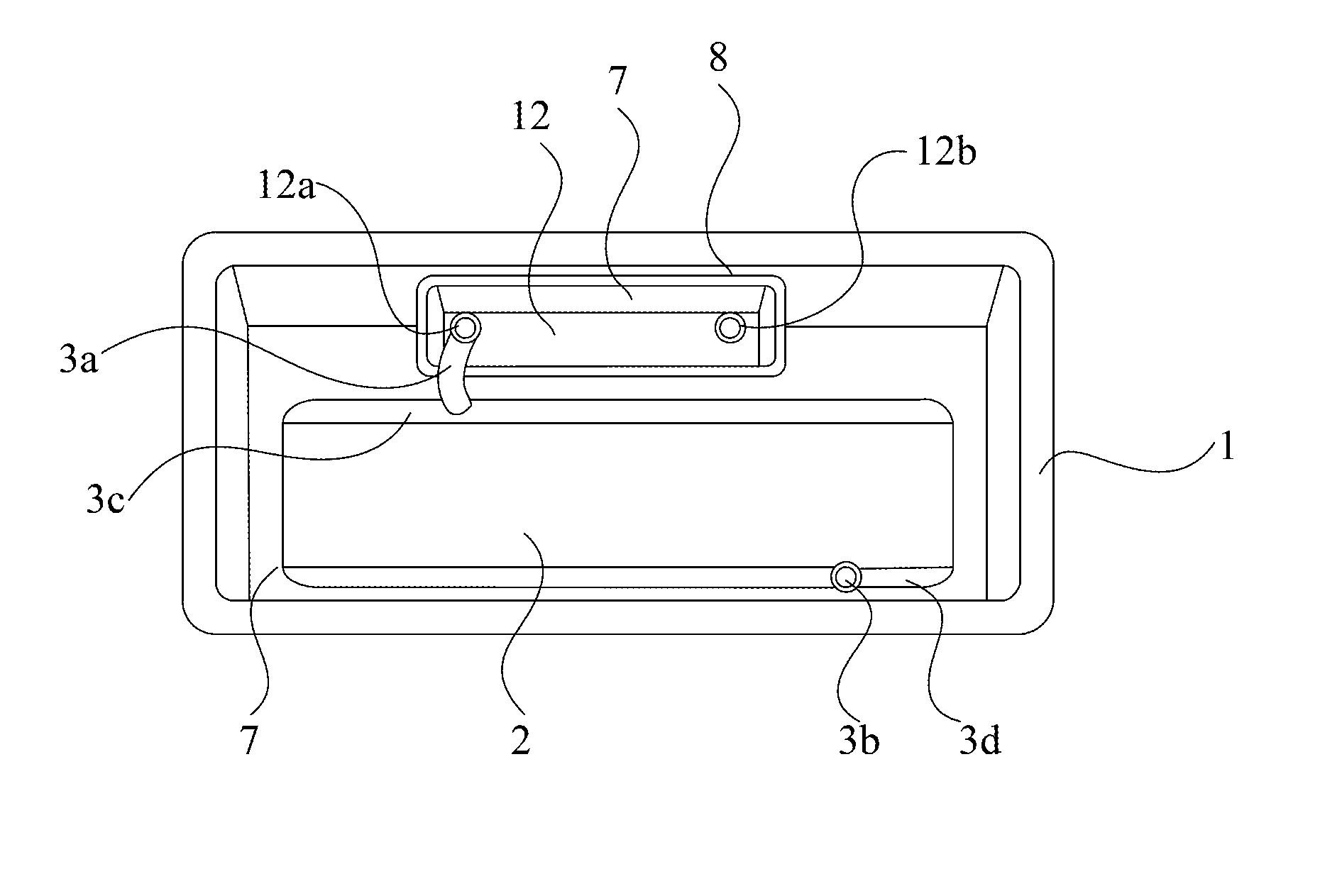
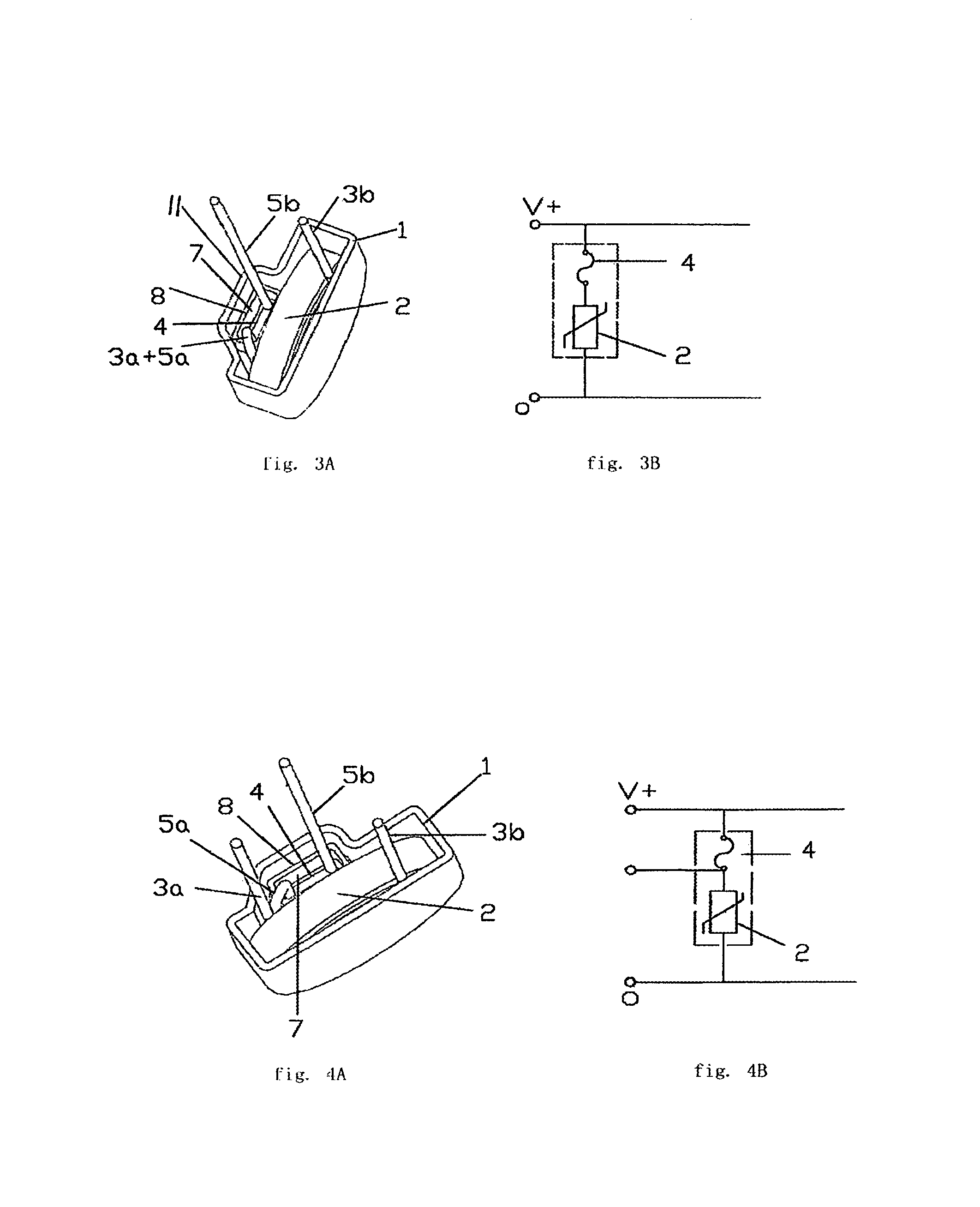
[0056]Shown in FIGS. 3A and 3B, is an embodiment with two leads, which comprises varistor 2, alloy-type thermal fuse 4, outer case 1 and inner case 8. The front wall of outer case 1 extends to the outside to form a raised section 11 for accommodating inner case 8 therein. Alloy-type thermal fuse 4 and melting promoting agent such as resin 7 are placed in inner case 8 which is made of ceramic or other material of high heat conduction and high electrical insulation. The opening of inner case 8 is sealed with epoxy resin 6 with the inner surface of inner case 8 attached to one surface of varistor 2. Inner case 8 and varistor 2 are placed in outer case 1 (as shown in FIG. 2B). First lead 3a of varistor 2 is connected with second lead 5a of alloy-type thermal fuse 4 and enclosed in the case. Second lead 3b of varistor 2 and first lead 5b of alloy-type thermal fuse 4 respectively extend to the outside of outer case 1. The opening of outer case 1 is sealed with epoxy resin 6 to form a clos...


PUM


Abstract

An electronic protection component comprises an outer case bounding an outer cavity therein; a varistor with a first varistor lead connected to a first varistor electrode and a second varistor lead connected to a second varistor electrode, wherein the varistor is placed in the outer cavity; a low melting point alloy wire with a first thermal fuse lead in one end and a second thermal fuse lead in the other end; wherein either the first thermal fuse lead or the second fuse lead is connected to either the first varistor electrode or the second varistor electrode therefore forming a lead junction.

Description

CROSS-REFERENCE TO RELATED APPLICATIONS[0001]This application is a continuation-in-part application Ser. No. 11 / 792,991, filed Jun. 13, 2007, which is incorporated herein by reference.TECHNICAL SCOPE[0002]The invention relates to a varistor with built-in alloy-type thermal fuse with thermal failure protection which is particularly applied to zinc oxide varistor and used for over-voltage protection.BACKGROUND OF THE INVENTION[0003]A varistor is broadly used as an over-voltage protection component and surge absorption component for circuit, equipment and components because of its non-linear volt-ampere character. Irrespective whether the varistor is used in power circuitry or electrical circuitry, if transient over-voltage happens frequently, the varistor will operate frequently to protect electrical equipment and components by suppressing the amplitude of the over-voltage, absorbing and releasing the surge power. However, the frequent operation will inevitably cause the performance d...

Claims


Application Information

Patent Timeline
IPC IPC(8): H01C7/10
CPCH01C7/126
Inventor XU, ZHONGHOU
Owner XIAMEN SET ELECTRONICS
Why Eureka
Try Eureka