
Device and method for thermal bonding of a textile web

a textile web and thermal bonding technology, applied in drying machines with progressive movements, lighting and heating apparatus, liquid/gas/vapor treatment of indefinite length materials, etc., can solve the problems of affecting the thermal bonding effect of the textile web. , the effect of reducing the temperature profile of the web

Active Publication Date: 2018-12-25
TRÜTZSCHLER GRP SE
View PDF14 Cites 1 Cited by
  • Summary
  • Abstract
  • Description
  • Claims
  • Application Information

AI Technical Summary

Benefits of technology

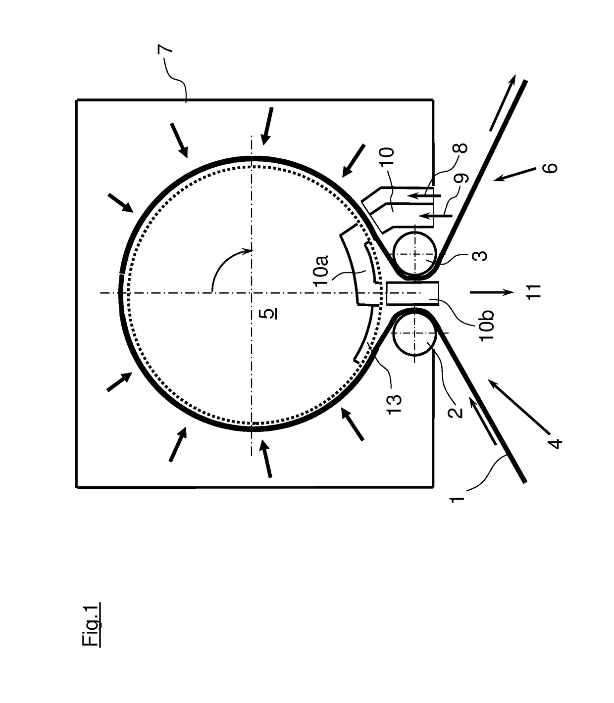
[0012]In this, the cooling air is directed by means of a channel and / or nozzle onto the web. In that way, the region of cooling on the web can be localized, whereby the effectiveness of the bonding plant is not impaired as a large as possible circumferential area of the through-air drum is used for the bonding. The web is cooled by the channel or nozzle over the entire working width.
[0013]In a preferred embodiment, the cooling air flows through the web and the through-air drum. This lowers the temperature profile of the web at both sides and is no longer warmed by the through-air drum. The web is therefore cooled over the entire cross-section over the working width, by which the fibers or filaments are bonded and shrink slightly.
[0015]It is advantageous that the air system is formed as an at least partially closed redirection arranged inside the through-air drum and with which the cooling air is again extracted from the bonding plant. The air system therefore limits the cooling effect to a small area of the through-air drum, so that this is only cooled locally.
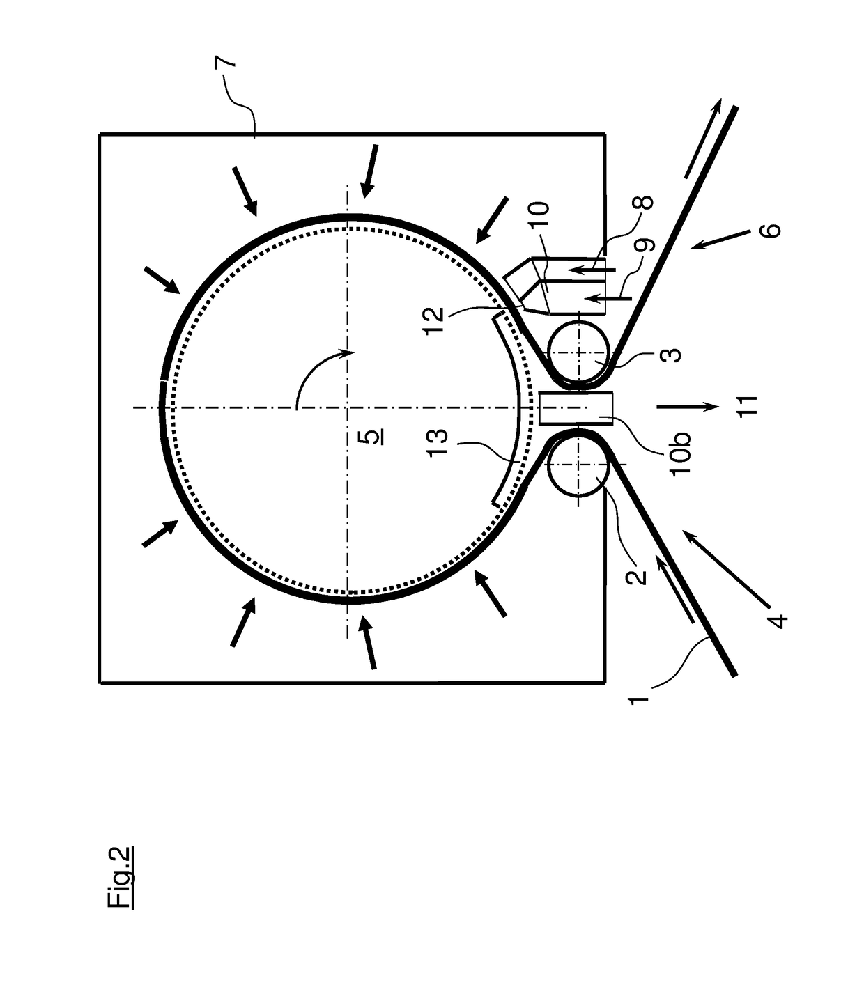
[0016]The formation of the air system as a closed channel has the advantage the cooling air only occurs at two limited areas of the through-air drum, which is advantageous for the temperature level of the through-air drum and the energy balance of the bonding plant is not significantly affected.
[0017]The use of the shielding plate to redirect the cooling air has the advantage of the retrofitting capability of the bonding plant, as all necessary add-ons and supplements can take place outside the bonding plant. Should the shielding plate have a dish-shaped convex or concave form, it requires little effort to replace the existing shielding plate with this without having to reconstruct the bonding plant.

Problems solved by technology

With the negative pressure, high temperature and loss of moisture, the web tends to adhere to the drum resulting in the operating speed having to be reduced and resulting in damage to the web.
The air from the cooling drum can then get into the drum and mix there with the warm air—which is not efficient.

Method used


Image

  • Device and method for thermal bonding of a textile web
  • Device and method for thermal bonding of a textile web

Examples


Embodiment Construction

[0022]FIG. 1 shows an Omega design bonding plant operated with hot air. The web 1 to be bonded runs in the run-in section 4 over an idler drum 2 that can be embodied as extraction drum into the bonding plant, runs around the air-permeable-designed through-air drum 5 in the clockwise direction and then runs over a cooling drum 3 in the run-out region 6 of the bonding plant. The through-air drum 5, the idler drum 2 and the cooling drum 3 can be arranged in a common housing 7 into which hot fresh air 8 is fed via one or more inlet flow openings. The hot fresh air 8 flows through the web 1, so heating the web; the air is then extracted by a fan, not shown in the figure, located in the end face of the through-air drum 5. In this, the through-air drum 5 is operated at negative pressure so that different flow conditions occur in the bonding plant.

[0023]To prevent the web 1 adhering to the through-air drum 5, the invention provides for the web 1 to be cooled shortly before the detachment fr...


PUM

PropertyMeasurementUnit
diameteraaaaaaaaaa
diameteraaaaaaaaaa
areaaaaaaaaaaa

Abstract

The invention relates to a device and a method for the bonding of a textile web, whereby the textile web is guided over an idler drum into a bonding plant, led around a through-air drum and over a cooling drum and then led out again, whereby heated fresh air flows through the web and the through-air drum and the exhaust air is extracted from the bonding plant. According to the invention, it is intended that cooling air is directed onto the web ahead of the detachment point of the web from the through-air drum onto the web.

Description

CROSS-REFERENCE TO RELATED APPLICATIONS[0001]This application is a U.S. National Stage of International Patent Application No: PCT / EP2014 / 002254 filed Aug. 16, 2014, designating the United States and claiming benefit of German Patent Application No. 10 2013 114 075.0 filed Dec. 16, 2013.BACKGROUND OF THE INVENTION[0002]The invention relates to a device and a method for the thermal bonding of a textile web, whereby the textile web is guided over an idler drum in a bonding plant, then round a through-air drum and over a cooling drum before being guided out again.[0003]In these thermal bonding plants, nonwovens made from or with thermoplastic fibers are heat set or bonded by means of hot air, saturated steam or hot water in order to reduce stresses in the web and fix the fibers. In this, warmed-up air is fed to a processing space, whereby the fresh air is led through the web into a through-air drum and then extracted via a fan. The fresh air absorbs the moisture from the web and heats ...

Claims


Application Information

Patent Timeline
Patent Type & Authority Patents(United States)
IPC IPC(8): B32B38/10D06C7/00D04H1/54F26B13/16D06B5/08D04H3/16B32B43/00D06C29/00D04H3/11F26B13/00F26B21/00D06C7/02F26B23/00B29K105/06
CPCD06B5/08D06C7/00F26B13/16D04H1/54F26B23/002B29K2105/06B32B38/10B32B43/006D04H3/11D04H3/16D06C7/02D06C29/00F26B13/00F26B21/004F26B23/00
Inventor WEIGERT, THOMASLIEBSCHER, WILLIHAJDU, STEPHAN
Owner TRÜTZSCHLER GRP SE
Learn More