Gas sensor element and gas sensor

Active Publication Date: 2018-12-25
NGK SPARK PLUG CO LTD
View PDF22 Cites 5 Cited by
  • Summary
  • Abstract
  • Description
  • Claims
  • Application Information

AI Technical Summary

Benefits of technology

[0025]According to the invention, a gas sensor element can be obtained including a porous protective layer having an inside region and an outside region which is resistant to peeling even when covering a tubular gas sensor element.

Problems solved by technology

However, this porous protective layer is easily peeled from a solid electrolyte body when applied to a tubular gas sensor element.

Method used


Image

  • Gas sensor element and gas sensor
  • Gas sensor element and gas sensor
  • Gas sensor element and gas sensor

Examples


example 1

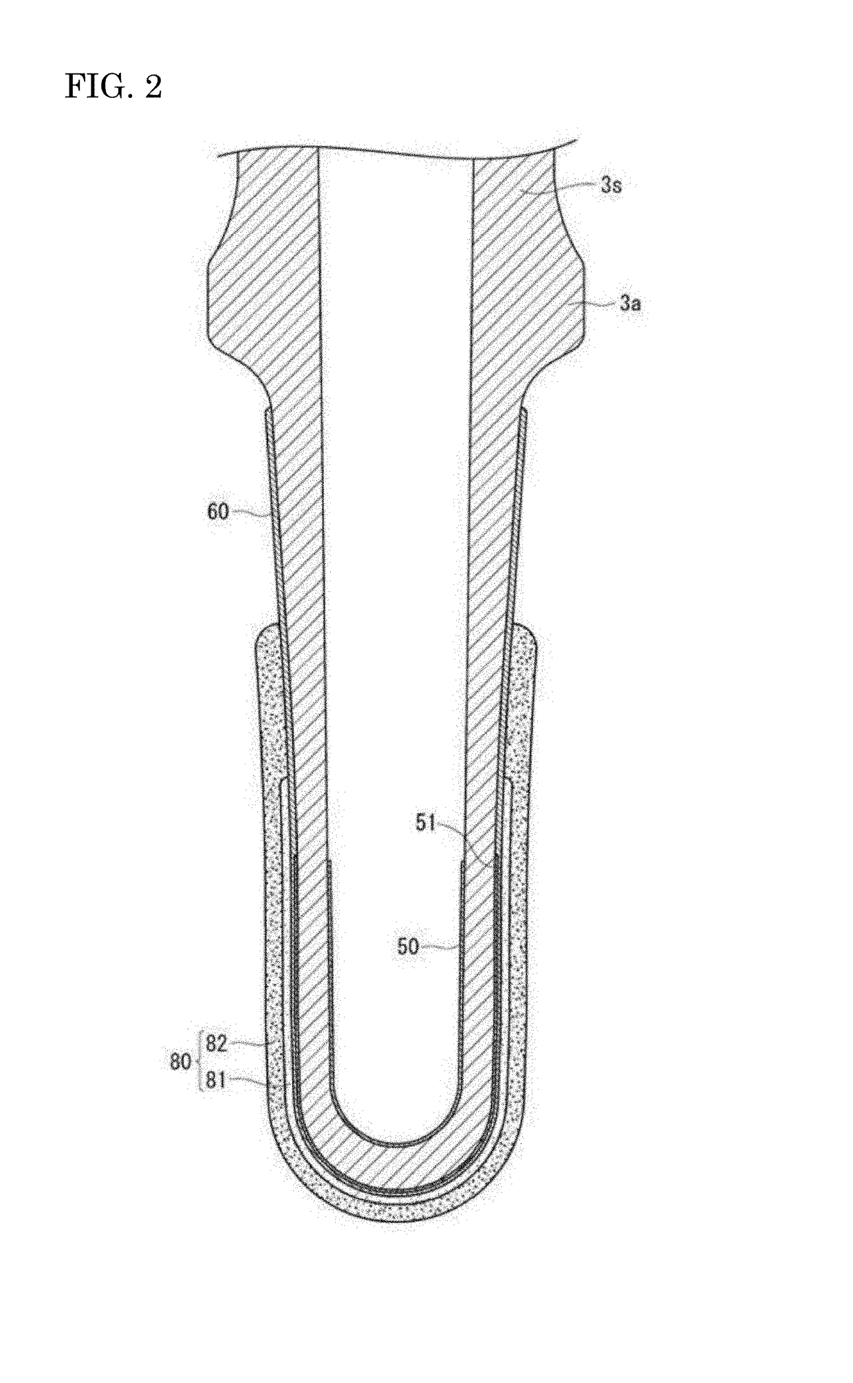
[0083]A solid electrolyte body 3s formed of partially stabilized zirconia, in which 5 mol % of Y2O3 was added to ZrO2, and having a bottomed cylindrical shape as shown in FIGS. 1 and 2 was prepared. Next, an inside electrode 50 made of Pt was formed on an inner circumferential surface of the solid electrolyte body 3s using an electroless plating method. Similarly, an outside electrode 51 made of Pt was formed on the front end side of an outer circumferential surface of the solid electrolyte body 3s using the electroless plating method.

[0084]Next, a ceramic (spinel or the like) sprayed layer 60 was formed (thickness: 150 μm) to cover the outside electrode 51.

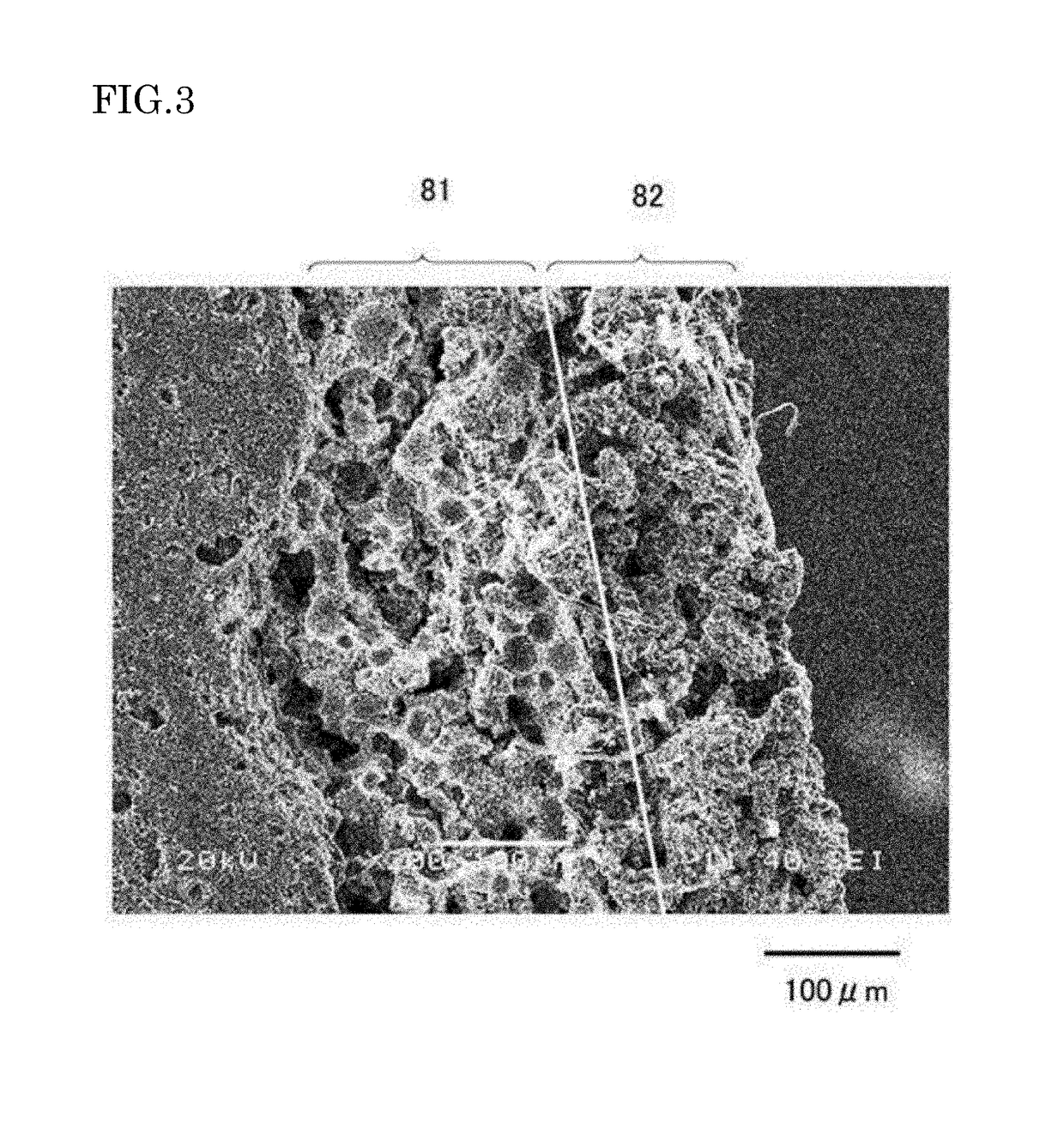
[0085]Next, using a dipping method, an inside paste that becomes an inside region 81 was applied (thickness: 250 μm) onto the sprayed layer 60 to cover the outside electrode 51. In the inside paste, only spinel (average particle diameter: 30 μm) was used as ceramic particles, and in this embodiment, glass was not added to the ins...

example 2

[0094]A solid electrolyte body 3s similar to that of Example 1 was prepared, and similarly to Example 1, an inside electrode 50, an outside electrode 51 and a sprayed layer 60 were formed.

[0095]Next, by a dipping method, an inside paste to be an inside region 81 was applied (thickness: 250 μm) onto the sprayed layer 60 to cover the outside electrode 51. In the inside paste, only spinel (average particle diameter: 30 μm) was used as the ceramic particles, and in this embodiment, glass formed of zircon-based glass was further mixed therein at a mixing ratio (mass ratio) of 10 wt % of glass to 100 wt % of ceramic.

[0096]Next, an outside paste to be an outside region 82 was applied (thickness: 450 μm) to a surface of the inside paste, and the entire outside paste was fired at 1000° C. To prepare a slurry for forming the outside paste, spinel (average particle diameter: 30 μm) and titania (average particle diameter: 0.1 μm) were mixed at a mixing ratio of 70 vol % of spinel and 30 vol % o...

example 3

[0101]A solid electrolyte body 3s similar to that of Example 2 was prepared, and similarly to Example 2, an inside electrode 50, an outside electrode 51 and a sprayed layer 60 were formed.

[0102]Next, by a dipping method, an inside paste that becomes an inside region 81 was applied (thickness: 250 μm) onto the sprayed layer 60 to cover the outside electrode 51, and the entire inside paste was fired at 1000° C. In the inside paste, only spinel (average particle diameter: 30 μm) was used as the ceramic particles, and in this embodiment, glass formed of zircon-based glass was further mixed therein at a mixing ratio (mass ratio) shown in Table 3 to 100 wt % of ceramic. In this manner, a gas sensor element was manufactured in which the inside region 81 was formed on a surface of the solid electrolyte body 3s.

[0103]The adhesion evaluation was performed on the gas sensor element thus obtained. A similar evaluation to that of Example 2 was performed as the adhesion evaluation. The results t...


PUM

PropertyMeasurementUnit
wt %aaaaaaaaaa
wt %aaaaaaaaaa
wt %aaaaaaaaaa

Abstract

A gas sensor element (3) includes: a solid electrolyte body (3s) having a bottomed tubular shape and a closed front end, and extending in the direction of an axial line O; an inside electrode (50) which is provided on an inner surface of the solid electrolyte body; an outside electrode (51) which is provided on an outer surface of the solid electrolyte body; and a porous protective layer (80) which covers the outside electrode, the porous protective layer has an inside region (81) which covers the outside electrode and an outside region (82) which covers the inside region and has a lower porosity than the inside region, and the outside region is formed of a sintered body of ceramic and glass.

Description

BACKGROUND OF THE INVENTION[0001]1. Field of the Invention[0002]The present invention relates to a gas sensor element and a gas sensor which detects a concentration of a detecting gas.[0003]2. Description of the Related Art[0004]A sensor in which a substantially cylindrical gas sensor element extending in an axial direction and having a closed front end is inserted into and held in a tubular main metal fitting has been known as a gas sensor which detects an oxygen concentration in an exhaust gas of a vehicle or the like (see JP 2012-37445A). This gas sensor element has a tubular solid electrolyte body (hereinafter, also referred to as an element main body), and an inside electrode and an outside electrode which are formed on inner and outer surfaces of the solid electrolyte body, respectively. The outer surface of the solid electrolyte body is covered with a porous protective layer for protecting the outside electrode from poisoning or the like (see JP-H11-72460A).[0005]A technique ...

Claims


Application Information

Patent Timeline
Patent Type & Authority Patents(United States)
IPC IPC(8): G01N27/407G01N27/409
CPCG01N27/409G01N27/4077
Inventor ISHIKAWA, TAKANORIYAMADA, NAOKISHIONO, KOJI
Owner NGK SPARK PLUG CO LTD
Why Eureka
Try Eureka