Handle assembly for a vacuum cleaner

a technology for vacuum cleaners and handles, which is applied in the direction of suction handles, mechanical suction control, suction cleaners, etc., can solve the problems of noise generated by the second airflow and away from the user, and achieve the effect of improving the aesthetics of the handle assembly, and reducing the risk of dust and other dirt jamming

Inactive Publication Date: 2019-01-01
DYSON TECH LTD
View PDF10 Cites 0 Cited by
  • Summary
  • Abstract
  • Description
  • Claims
  • Application Information

AI Technical Summary

Benefits of technology

[0005]Owing to the provision of the cover and the location of the holes, the noise generated by the second airflow may be reduced. In particular, by locating the holes in a lower part of the cover, the noise generated by the second airflow may be directed away from the handle and thus away from the user.
[0006]The valve may pivot between the closed position and the open position. This then has the advantage of providing a relatively compact arrangement. In particular, the space between the cover and the duct that is required for movement of the valve may be kept relatively small. Pivoting of the valve may be achieved by pivotally attaching a first end of the valve to the duct or cover. Actuating the actuator may then cause a second opposite end of the valve to lift.
[0008]The actuator may comprise a trigger attached to a rod, the rod may be housed inside the handle, and the rod may be attached to the valve. The only part of the valve assembly that is visible is therefore the trigger. Not only does this improve the aesthetic of the handle assembly, but it reduces the risk of dust and other dirt jamming the actuator.
[0009]The bleed aperture may face towards the handle. As a result, the valve assembly may be kept relatively simple. In particular, a relatively short and direct path may be taken between the actuator and the valve. In spite of the bleed aperture facing the handle, the cover ensures that the noise of the second airflow entering the bleed aperture is muffled and that the noise of the second airflow entering the holes is directed away from the handle.
[0010]The valve assembly may comprise a spring that biases the valve to the closed position. As a result, the bleed aperture is closed automatically whenever the actuator is released. This then avoids the situation in which a user, unaware that the bleed aperture is open, assumes that the reduction in the primary airflow is the result of a performance issue with the vacuum cleaner.

Problems solved by technology

In particular, by locating the holes in a lower part of the cover, the noise generated by the second airflow may be directed away from the handle and thus away from the user.

Method used


Image

  • Handle assembly for a vacuum cleaner
  • Handle assembly for a vacuum cleaner
  • Handle assembly for a vacuum cleaner

Examples


Embodiment Construction

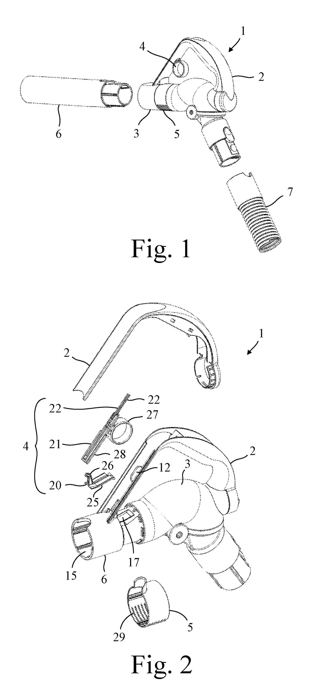
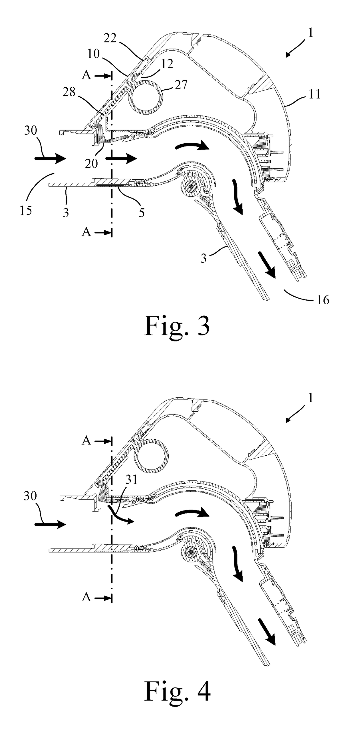
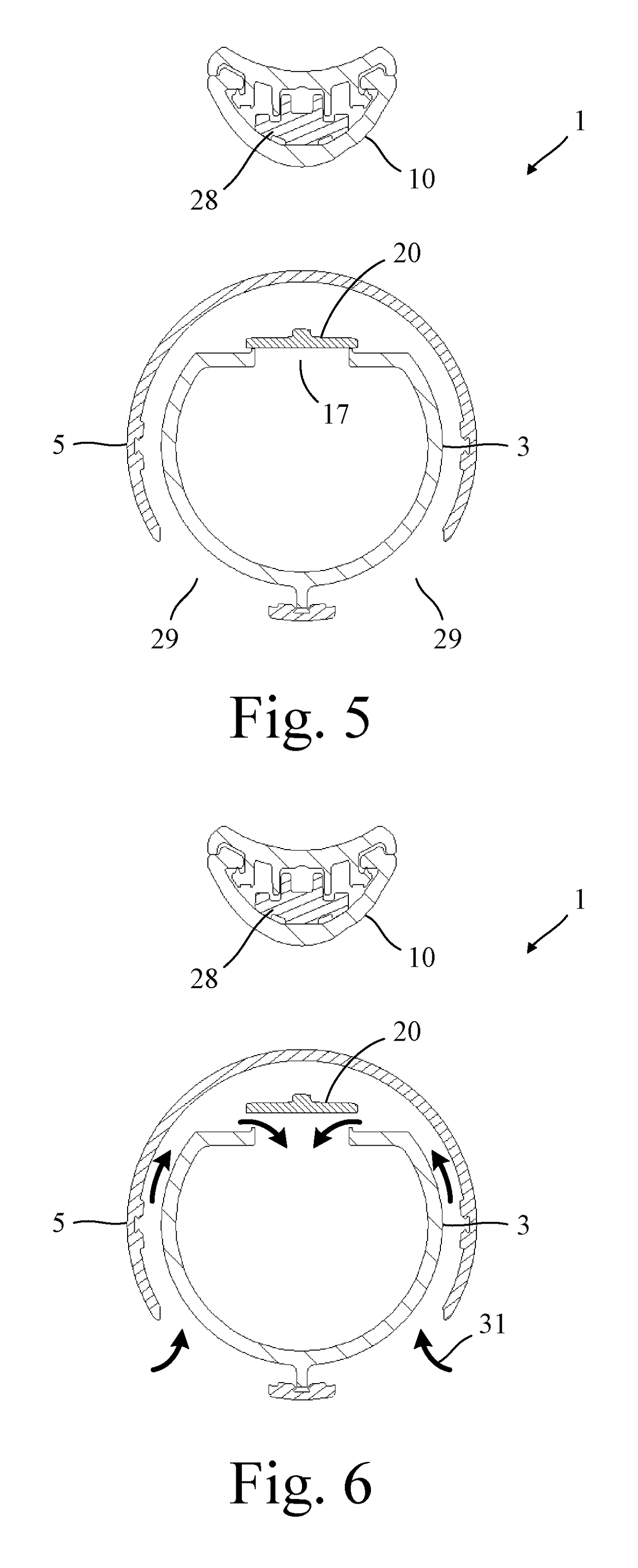
[0018]The handle assembly 1 of FIGS. 1 to 6 comprises a handle 2, a duct 3, a valve assembly 4, and a cover 5.

[0019]The handle 2 is attached to the duct 3 and comprises a first portion 10 and a second portion 11. The first portion 10 houses part of the valve assembly 4, which is described below in more detail, and the second portion 11 serves as a handgrip.

[0020]The duct 3 comprises a first end that is attachable to an elongate tube 6 or other attachment, and a second end that is attachable to a hose 7 of a vacuum cleaner (not shown). The duct 3 is composed of a number of sections that are joined together. This is done in order to provide relative rotation between the sections, which aids in the handling of the handle assembly 1. However, the provision of multiple sections is not pertinent to the present invention and the duct 3 might equally comprise a single section. The duct 3 comprises an inlet 15 at the first end, an outlet 16 at the second end, and a bleed aperture 17 located ...


PUM


Abstract

A handle assembly for a vacuum cleaner that includes a handle, a duct, a valve assembly, and a cover. The handle is attached to the duct, which has an inlet end, an outlet end, and a bleed aperture between. The valve assembly includes a valve and an actuator. The valve is moveable between closed and open positions by the actuator to close and open the bleed aperture. The cover surrounds the duct such that an upper part overlies the bleed aperture and valve. Holes are formed in a lower part of the cover. Suction at the outlet causes a primary airflow to be drawn into the duct via the inlet. When the valve is in the open position, the suction causes a secondary airflow to be drawn in through the holes, around the space between the duct and the cover, and into the duct via the bleed aperture.

Description

REFERENCE TO RELATED APPLICATION[0001]This application claims the priority of United Kingdom Application No. 1516665.5, filed Sep. 21, 2015, the entire contents of which are incorporated herein by reference.FIELD OF THE INVENTION[0002]The present invention relates to a handle assembly for a vacuum cleaner.BACKGROUND OF THE INVENTION[0003]The handle assembly of a vacuum cleaner may comprise a duct through which a primary airflow is carried. The duct may include a bleed aperture through which a secondary airflow is admitted. The flow rate of the primary airflow can then be controlled by opening and closing the bleed aperture. Unfortunately the noise generated by the second airflow is often unpleasant.SUMMARY OF THE INVENTION[0004]The present invention provides a handle assembly for a vacuum cleaner comprising a handle, a duct, a valve assembly, and a cover, wherein the handle is attached to the duct, the duct has an inlet at one end, an outlet at an opposite end, and a bleed aperture ...

Claims


Application Information

Patent Timeline
Patent Type & Authority Patents(United States)
IPC IPC(8): A47L9/32A47L9/00A47L9/24
CPCA47L9/32A47L9/0081A47L9/327A47L9/248A47L9/24A47L9/322A47L5/36A47L9/0072
Inventor BLANCHARD, OLIVER STANTONMCLUCKIE, PAUL ANDREW
Owner DYSON TECH LTD
Why Eureka
Try Eureka