
Method for allocating internet protocol addresses to clients of a network and corresponding apparatus

a network and protocol address technology, applied in the field of access points, can solve the problems of data communication loss, inability to ensure the coverage of the wireless network in all areas of the building or the home, and inability to communicate between the wireless access point and the wireless network client devi

Active Publication Date: 2019-01-01
INTERDIGITAL CE PATENT HLDG
View PDF11 Cites 0 Cited by
  • Summary
  • Abstract
  • Description
  • Claims
  • Application Information

AI Technical Summary

Benefits of technology

The present patent aims to improve the allocation of Internet Protocol addresses to network devices in a communication network. The method involves receiving a request for attribution of an Internet Protocol address from a network device and performing a Media Access Control address translation on the request. The translated Media Access Control address is then transmitted to the original network device. The method can also involve verifying if the translated Media Access Control address is not used by any other network devices and updating a list of allowable Media Access Control addresses for filtering. The Internet Protocol address server for allocation of Internet Protocol addresses to network devices in a communication network includes a network interface and a processor for applying a Media Access Control address translation and verifying if the translated Media Access Control address is not used by any other network devices. The technical effects of this patent include improved efficiency in the allocation of Internet Protocol addresses and reduced inconvenience for network devices.

Problems solved by technology

Consequently, good wireless network coverage in all areas of a building or a home can often not be ensured with a single wireless access point.
This causes data collisions that make data communication impossible between the wireless access point and the wireless network client device.
While this solves the above discussed problem of communication loss in areas of common coverage of the access point and of the wireless network extender, the MAC address translation causes a problem of communication loss when the client device roams from the wireless network extender to the access point to a coverage area that is only covered by the access point and the wireless access point is configured to function as a bridge.
As a consequence, any IP packets that are destined to the client device based on its previous IP address are lost, causing a communication disruption a.k.a.

Method used


Image

  • Method for allocating internet protocol addresses to clients of a network and corresponding apparatus
  • Method for allocating internet protocol addresses to clients of a network and corresponding apparatus
  • Method for allocating internet protocol addresses to clients of a network and corresponding apparatus

Examples


Embodiment Construction

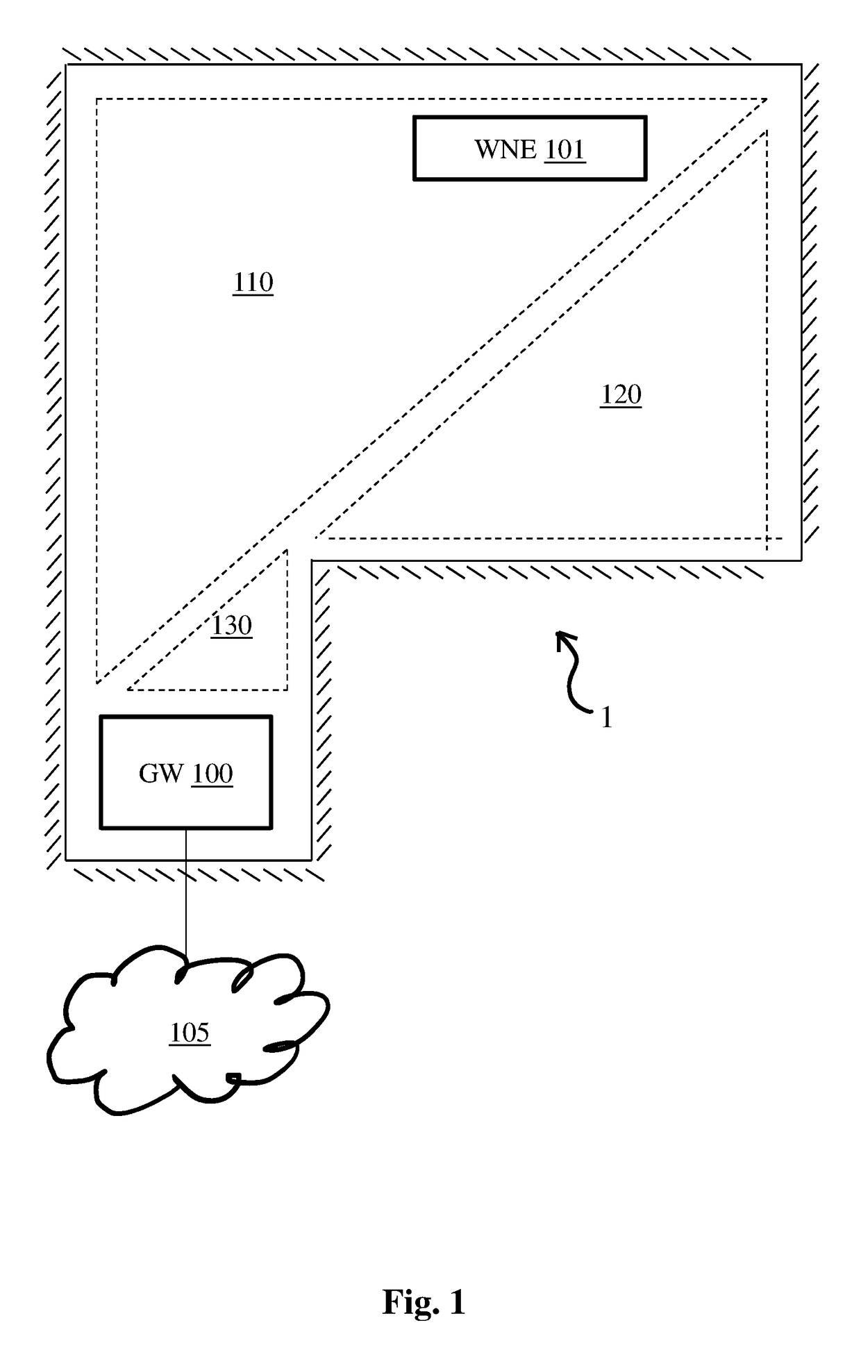
[0036]FIG. 1 is a space in a typical building, office or home 1, in which embodiments of the present principles can be applied. A gateway GW 100 and a wireless network extender WNE 101 provide wireless network client devices (not shown) with access to a local wireless network (LAN) and to a Wide Area Network (WAN) 105 such as the Internet. Broken lines delimit zones or areas 110, 120, 130 of wireless network coverage. These areas are delimited through attenuation by walls (note that reflection is not taken account of in this figure for reasons of legibility). Area 110 is covered by both the gateway GW 100 and the wireless network extender WNE 101. Area 120 is covered by the wireless network extender WNE 101 only. Area 130 is covered by the gateway GW 100 only.

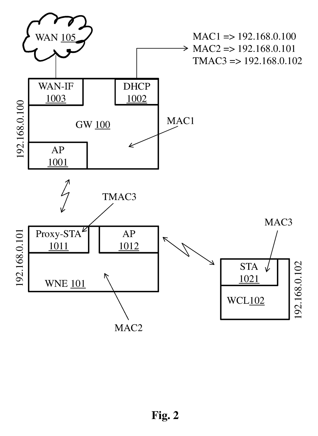
[0037]FIG. 2 is a block diagram of a typical network configuration in which embodiments of the present principles can be applied. The diagram comprises gateway GW 100, wireless network extender WNE 101, and a wireless network c...


PUM


Abstract

An access device and an extender access device, forming a network for network client devices. A single IP address attribution server in the network attributes IP addresses to network devices based on their MAC address. The access device providing access in a first coverage zone. The extender access device providing access in a second coverage zone. The extender access device implements MAC address translation for representing network client devices in the second zone before the access device. When a network client device roams from the second zone to the first zone, the client device keeps its IP address that was attributed to it by the IP address attribution server via the extender access device even if the client device requests an IP address with its real, non-translated MAC address.

Description

[0001]This application claims the benefit, under 35 U.S.C. § 119 of European Patent Application No. 15305694.0, filed May 6, 2015.1. TECHNICAL FIELD[0002]The present disclosure generally relates to the field of data communication networks and in particular to access points (APs) in combination with network extenders.2. TECHNICAL BACKGROUND[0003]Wireless access points emit radio waves that are attenuated by furniture, doors, walls, windows, ceilings and floors. Consequently, good wireless network coverage in all areas of a building or a home can often not be ensured with a single wireless access point. For example, it is known that a wooden door attenuates a WiFi signal by 3 dB, which is half the signal strength, while a concrete wall or ceiling can attenuate a WiFi signal by as much as 10-15 dB (i.e., to about one eighth of the original signal). Attenuation is even more important in the presence of metal, such as tinted windows or steel reinforced concrete. Wireless network extender...

Claims


Application Information

Patent Timeline
Patent Type & Authority Patents(United States)
IPC IPC(8): H04L29/12H04L12/26H04L12/66H04L12/751H04W16/26H04W84/12H04L45/02
CPCH04L61/103H04L12/66H04L43/10H04L43/12H04L45/02H04L61/2007H04L61/2596H04L61/6022H04W16/26H04L61/2015H04W84/12H04L61/2038H04L61/2046H04L61/25H04L61/5007H04L2101/622H04L61/5038H04L61/5046H04L61/5014H04W8/26
Inventor JEANNE, LUDOVICTEROL, JOSEGRAEF, LUCIENVAN DEN BOSSCHE, GEERT
Owner INTERDIGITAL CE PATENT HLDG
Learn More