Pairing method in illumination system, illumination system, and illumination controller

a technology of illumination system and illumination controller, which is applied in the direction of transmission system, electric lighting source, instruments, etc., can solve the problems of requiring an enormous amount of effort, limited radio wave emitted limited the area that can be reached by the access device, etc., and achieves efficient pairing

Active Publication Date: 2019-01-01
PANASONIC INTELLECTUAL PROPERTY MANAGEMENT CO LTD
View PDF8 Cites 0 Cited by
  • Summary
  • Abstract
  • Description
  • Claims
  • Application Information

AI Technical Summary

Benefits of technology

[0010]It is possible to efficiently perform pairing between luminaires and access devices in an illumination system.

Problems solved by technology

However, the region that the radio waves emitted from the access devices can reach is limited.
Moreover, a total number of luminaires which can be connected to one access device is also limited.
Therefore, an operator who conducts the pairing operation needs to conduct the pairing operation while checking the radio wave condition between the luminaires and the access devices as well as a total number of luminaires connected to the access devices, which requires an enormous amount of effort.

Method used


Image

  • Pairing method in illumination system, illumination system, and illumination controller
  • Pairing method in illumination system, illumination system, and illumination controller
  • Pairing method in illumination system, illumination system, and illumination controller

Examples


embodiment

[1-1. Overall Configuration of Illumination System]

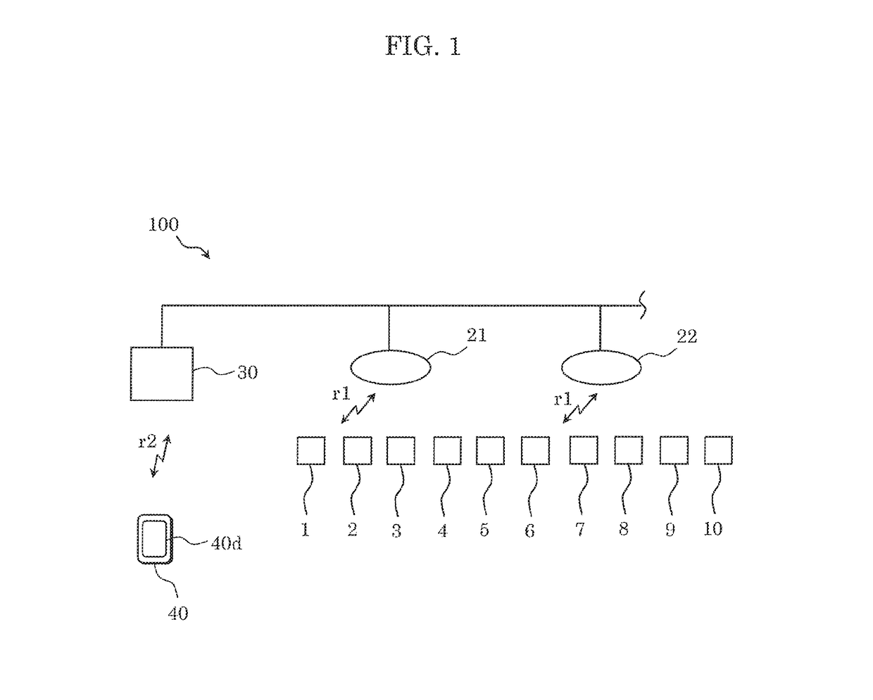
[0021]FIG. 1 is a diagram illustrating illumination system 100 according to an embodiment.

[0022]Illumination system 100 includes a plurality of luminaires 1, 2, 3, 4, 5, 6, 7, 8, 9, and 10, a plurality of access devices 21 and 22 that wirelessly communicate with one or more luminaires included in luminaires 1 to 10, and illumination controller 30 that communicates with the plurality of access devices 21 and 22. Further, illumination system 100 includes operation terminal 40 that communicates with illumination controller 30.

[0023]Note that although FIG. 1 illustrates ten luminaires 1 to 10 as an example, in reality, a hundred or more luminaires may be installed in a building part (such as a ceiling). Further, although FIG. 1 illustrates two access devices 21 and 22 as an example, in reality, three or more access devices may be installed in a building part, for example.

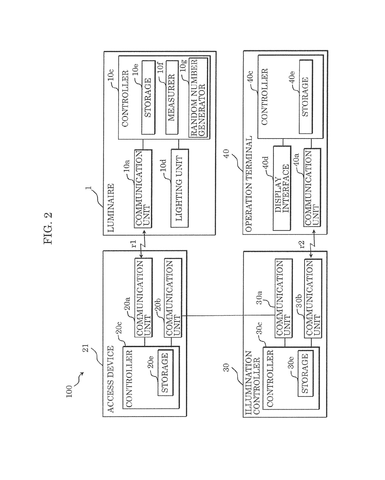
[0024]First, with reference to FIG. 1, the following describes com...


PUM


Abstract

Access devices broadcast a first command signal, and each of luminaires transmits first information as a reply to access devices. The first information includes identification information of the luminaire and a radio field intensity of the first command signal. After receiving plural pieces of the first information, each access device transmits second information to an illumination controller. The second information includes identification information of the access device and the plural pieces of the first information. The illumination controller: determines, when determining that a predetermined luminaire has transmitted the first information to only one access device, that the predetermined luminaire and the one access device are to be paired; and determines, when determining that the predetermined luminaire has transmitted the first information to the plural access devices, that the predetermined luminaire and an access device among the plural access devices which has a highest radio field intensity are to be paired.

Description

CROSS REFERENCE TO RELATED APPLICATION[0001]This application claims the benefit of priority of Japanese Patent Application Number 2017-130255 filed on Jul. 3, 2017, the entire content of which is hereby incorporated by reference.BACKGROUND1. Technical Field[0002]The present disclosure relates to: an illumination system including luminaires, access devices, and an illumination controller; a pairing method in the illumination system; and the illumination controller.2. Description of the Related Art[0003]Conventionally, an illumination system including a plurality of luminaires and a plurality of access devices that communicate with the plurality of luminaires by radio waves has been known (see Japanese Unexamined Patent Application Publication No. 2016-178014 (Patent Literature (PTL) 1)). With this type of illumination system, pairing between the plurality of access devices and the plurality of luminaires is performed using radio waves after the luminaires and the access devices are i...

Claims


Application Information

Patent Timeline
Patent Type & Authority Patents(United States)
IPC IPC(8): H05B37/02H04L12/28G06F3/0484G08C17/02G08C23/04H04W4/80
CPCH05B37/0272G06F3/04847G08C17/02H04L12/2807H04L12/2803G08C2201/93G08C23/04H04W4/80H05B47/175H05B47/19
Inventor HIDAKA, YUTO
Owner PANASONIC INTELLECTUAL PROPERTY MANAGEMENT CO LTD
Why Eureka
Try Eureka