Three dimensional workpiece support and drill jig alignment device for placement of weight loading channels in the body of a model car

a three-dimensional workpiece and alignment device technology, applied in drill jigs, toys, entertainment, etc., can solve the problems of limited access to prior art techniques for precision channel alignment utilizing machine shop tools such as drill presses or cnc machining, and the participation of cub scouts is limited

Inactive Publication Date: 2019-01-08
CATTANEO STEPHEN
View PDF19 Cites 9 Cited by
  • Summary
  • Abstract
  • Description
  • Claims
  • Application Information

AI Technical Summary

Benefits of technology

[0024]The three dimensional workpiece support / drill jig alignment device is basically an L-shaped housing embodiment with a sliding upper rectangular platform with a lateral workpiece support column providing three dimensional support to a small hand-held workpiece. The basic L-shaped housing provides two dimensional support at the bottom and front or back edge of the workpiece while the L-shaped, sliding upper rectangular platform provides a third lateral support column. This provides for a fixed placement and positioning of the model car workpiece which is linearly aligned with the drill bit guide in the vertical column of the L-shaped housing. Incremental lateral sliding of the upper platform to a predetermined location provides for the drilling of multiple, adjacent, parallel and aligned channels.
[0026]Moreover, the device provides for support to model cars designed and carved with irregular shapes keeping them in position to produce parallel, immediately adjacent and aligned channels for a specific weight loading purpose.
[0029]The device can be manufactured cost effectively. A prototype has been produced and utilized with ease and precision.

Problems solved by technology

Access to prior art techniques for precision channel alignment utilizing machine shop tools such as a drill press or CNC machining may be limited.
Cub Scout participation is therefore limited in a project and event promoting Scout participation.

Method used


Image

  • Three dimensional workpiece support and drill jig alignment device for placement of weight loading channels in the body of a model car
  • Three dimensional workpiece support and drill jig alignment device for placement of weight loading channels in the body of a model car
  • Three dimensional workpiece support and drill jig alignment device for placement of weight loading channels in the body of a model car

Examples


Embodiment Construction

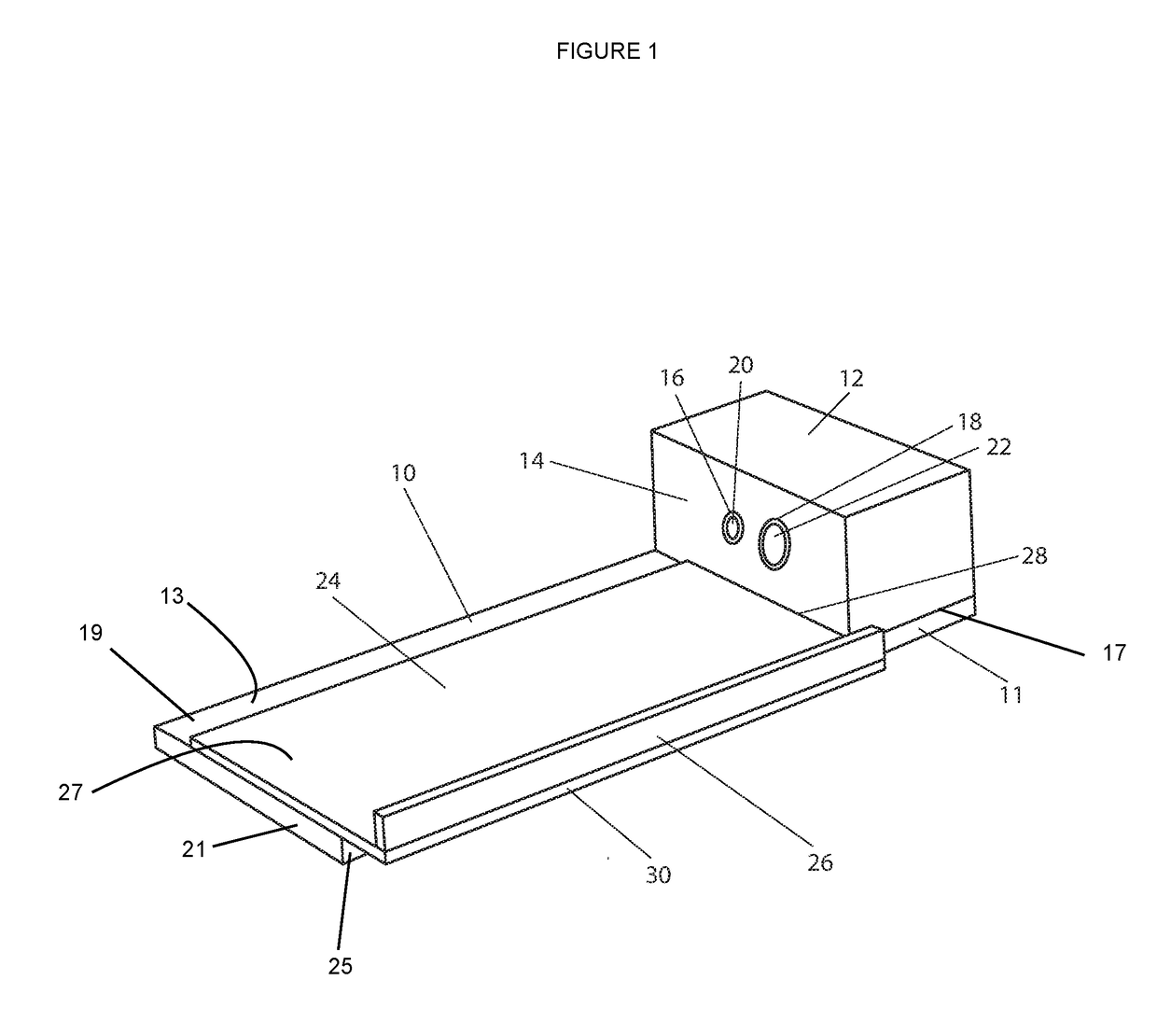
[0041]FIG. 1 shows a perspective view of a three dimensional workpiece support / drill jig alignment embodiment.

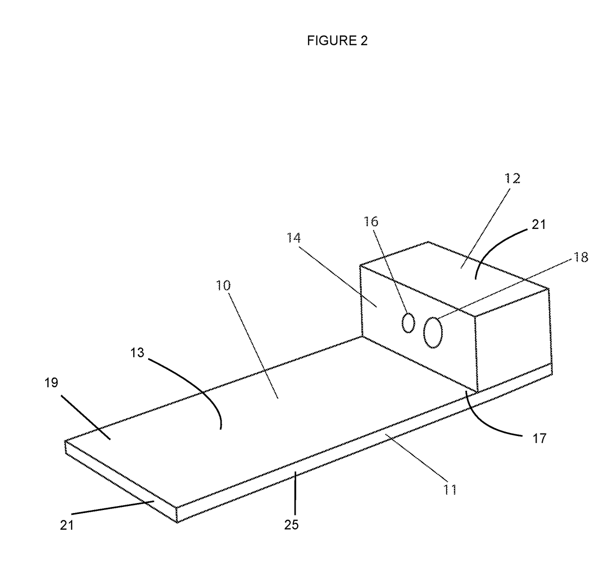
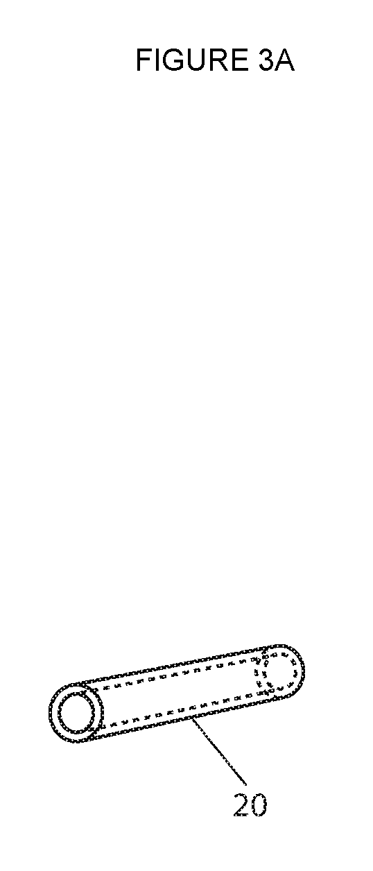
[0042]FIGS. 1, 2, 5, 6 and 9 show referenced parts of the claimed invention, and include: rectangular base platform 10, having a long edge 11 (of rectangular base platform), a vertical sleeve bearing column 12, the base platform having a top surface 13, the sleeve bearing column having a Front face 14, the base platform having a bottom surface 15, the column having a small sleeve bearing pilot hole 16, the base platform having a first end 17, the column having a large sleeve bearing hole 18, the base platform having a second end 19, the pilot hole having a small sleeve bearing 20, the column having a top surface 21, the large sleeve having a large sleeve bearing 22, the base platform having a back edge 23, a sliding upper rectangular (sliding) platform 24, the column having a back face 25, the sliding platform having a lateral workpiece support guide 26, the sliding platform...


PUM


Abstract

The embodiment is an L-shaped housing with a configuration that provides both for support to a small hand-held workpiece and to specific drill bit alignment toward the task of placing multiple, immediately adjacent, aligned channels within the body of a model car. To optimize car speed in the Pinewood Derby event, the child can specifically align and strategically place channels in the model car for the optimal loading of cylindrical weights. As an alternative to free-hand drilling with an attempt at sighting drill bit direction in two planes, the device provides for precise drill bit alignment to small hand-held workpieces. As an alternative to more complex drill jig and machine shop equipment, the device enables a child to safely and effectively introduce multiple, aligned channels with precision into the model car.

Description

BACKGROUND[0001]Field of the Invention[0002]The invention relates to a platform for aligning a drill bit.[0003]Description of the Prior Art[0004]The Pinewood Derby is an annual Boy Scouts of America event which provides the opportunity for over one million Cub Scouts and their parents, in a team effort, to design and prepare a winning derby car. Other organizations participate in similar model car racing events including Awana Grand Prix, Awana international, Native American Sons and Daughters, Kub Kar scouting. This is our audience.[0005]Children, 7 through 11 ½ years of age, along with a parent, work together to develop a model wooden car with emphasis on design and / or speed. For speed there are basic principles of weight distribution generally providing for weight loading toward the rear of the car to optimize the potential energy. Racing rules generally permit a maximum car weight of 5 ounces. Moreover, weights added on to the top and bottom surfaces of the car to achieve the op...

Claims


Application Information

Patent Timeline
Patent Type & Authority Patents(United States)
IPC IPC(8): B23B47/28A63H17/00
CPCA63H17/002B23B47/28
Inventor CATTANEO, STEPHEN
Owner CATTANEO STEPHEN
Why Eureka
Try Eureka