Eureka AIR delivers breakthrough ideas for toughest innovation challenges, trusted by R&D personnel around the world.

Scrap iron compression equipment for machining workshop

A compression equipment and machining technology, which is applied in the field of iron filings compression equipment in machining workshops, can solve the problems of large machining allowance, large iron filing volume, inconvenient handling and transportation of iron filings, etc., and achieves low production cost and reasonable structure. Simple, full-featured effects

Pending Publication Date: 2019-01-18
NANTONG INST OF TECH
View PDF0 Cites 5 Cited by
  • Summary
  • Abstract
  • Description
  • Claims
  • Application Information

AI Technical Summary

Problems solved by technology

In the mechanical processing manufacturing industry, the processing of machinery, especially the processing of blanks, has a large machining allowance, which will produce a large amount of iron filings left by mechanical processing. It is necessary to clean the iron filings regularly, but usually the iron filings They are very large and will soon fill up the scrap recycling box, which is not convenient for the handling and transportation of scrap iron in the later stage, so a scrap compression equipment is needed

Method used


Image

  • Scrap iron compression equipment for machining workshop

Examples


Embodiment Construction

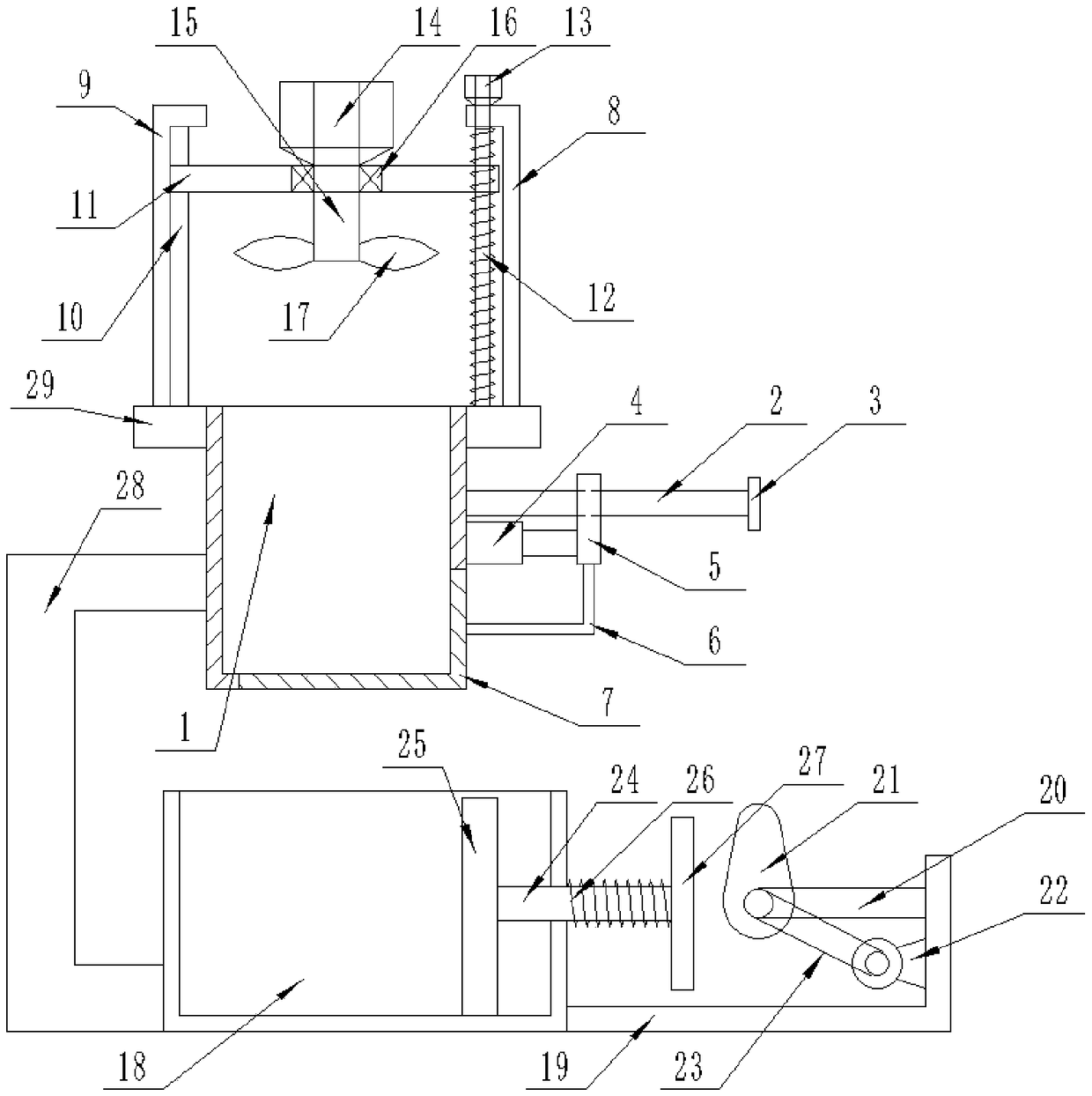
[0012] Such as figure 1 As shown, this specific embodiment adopts the following technical solutions: a kind of iron chip compression equipment for machining workshops, including a crushing chamber 1, a pin shaft 2, a limit block 3, a hydraulic cylinder 4, a shaft sleeve 5, and an L-shaped connecting rod 6 , bottom cover 7, right cover 8, left cover 9, slide rail 10, lifting platform 11, lead screw 12, first motor 13, second motor 14, rotating shaft 15, bearing 16, crushing blade 17, compression chamber 18 , side chamber 19, cam lever 20, cam 21, third motor 22, belt 23, push rod 24, briquetting block 25, spring 26, contact plate 27, concave word connecting rod 28 and platform 29; the right side of the crushing chamber 1 A pin shaft 2 and a hydraulic cylinder 4 are fixedly connected to the middle end of the side, a limit block 3 is fixedly connected to the other end of the pin shaft 2, and a bushing 5 is slidably connected to the pin shaft 2, so The bushing 5 is fixedly connec...


PUM


Abstract

The invention discloses scrap iron compression equipment for a machining workshop. The scrap iron compression equipment has a reasonable and simple structure, low production cost, convenient mountingand complete functions, and can effectively crush and compress scrap iron to facilitate handling and transportation later. The scrap iron compression equipment is characterized in that the scrap ironis put into a crushing chamber, then a lead screw is driven by a first motor to rotate, the height of a lifting platform is controlled, so a crushing cutting blade extends into the crushing chamber; arotating shaft is driven by a second motor to rotate, the scrap iron is crushed by the crushing cutting blade on the rotating shaft, a hydraulic cylinder operates after crushing to propel a shaft sleeve, so a bottom cap is separated from the crushing chamber, and the crushed scrap iron in the crushing chamber enters a compression chamber; and a third motor drives a cam to rotate by a belt, the cam knocks a contact plate, and meanwhile, under the action of a spring, a press block moves from left to right to realize reciprocating compression of the scrap iron. By the technical scheme, defects in the background art are effectively solved.

Description

Technical field: [0001] The invention relates to the technical field of machining, in particular to iron scrap compression equipment for machining workshops. Background technique: [0002] Machining refers to the process of changing the shape or performance of a workpiece through a mechanical device. According to the difference in processing method, it can be divided into cutting processing and pressure processing. In the mechanical processing manufacturing industry, the processing of machinery, especially the processing of blanks, has a large machining allowance, which will produce a large amount of iron filings left by mechanical processing. It is necessary to clean the iron filings regularly, but usually the iron filings They are large in size and will soon fill up the iron filings recycling box, which is not convenient for the handling and transportation of iron filings in the later stage, so a kind of iron filings compression equipment is needed. Invention content: ...

Claims


Application Information

Patent Timeline
IPC IPC(8): B02C18/10B02C18/16B30B9/32
CPCB02C18/10B02C18/16B30B9/327
Inventor 夏建平康徐红周修鹏
Owner NANTONG INST OF TECH
Why Eureka
Eureka Blog
Learn More