Device for use in the handling of a load and method for producing such a device

a technology for handling devices and load, which is applied in the direction of manipulators, programmed manipulators, manufacturing tools, etc., can solve the problems of long downtime of production plants, comparatively time-consuming refitting of production plants between different gripper tools each designed for specific gripping tasks, and low weight of gripper tools presently used in such production plants. , to achieve the effect of low cost, low weight and flexible adaptability

Active Publication Date: 2019-01-08
FFT PRODIONSSYST
View PDF12 Cites 70 Cited by
  • Summary
  • Abstract
  • Description
  • Claims
  • Application Information

AI Technical Summary

Benefits of technology

[0009]Therefore, it is the object of the present invention to provide a device for use in handling a load and a method for producing such a device with which the above-mentioned problems can be solved. In particular, a device and a method for use in handling a load and a method for producing such a device shall be provided in which the device has a low weight, is very flexibly adaptable and producible with low costs in comparison to known devices.
[0011]The mentioned device has a very low weight, is producible simply and with low costs and is very flexible and easy adaptable. The device can be supplemented at desired positions, for example, by one or more cantilever arms for handling units, like in particular a gripper, by roughening the fiber-reinforced plastics and thereby is prepared for docking a further gripper arm. In this way, a repair of the device is also easily possible. Herein, also fastening units, like bore holes for screws, etc., riveting, etc., can be fastened to the framework.
[0013]In the above-described device, the framework is composed of arbitrarily configurable single parts. The framework receives additional firmness and also the necessary stiffness by the cover or a jacket comprising the fiber-reinforced plastics.
[0016]In the above-described device, the single parts can be planar elements which comprise at least one plug unit with which the single parts can be assembled as the three-dimensional framework. Consequently, a light and low cost gripper system in plug construction is provided with the above-described device.
[0019]Preferably, the single parts of the framework of the device comprise an edge indentation. The edge indentation can better receive and compensate the torsion forces occurring in strain. Therewith, the stability of the framework made from the single parts can be still further increased.

Problems solved by technology

The gripper tools presently used in such production plants are comparatively heavy.
A further disadvantage lies in that a refitting of the production plant between different gripper tools which are each designed for specific gripping tasks is comparatively time consuming.
This leads to long downtimes of the production plant.

Method used


Image

  • Device for use in the handling of a load and method for producing such a device
  • Device for use in the handling of a load and method for producing such a device
  • Device for use in the handling of a load and method for producing such a device

Examples


first embodiment

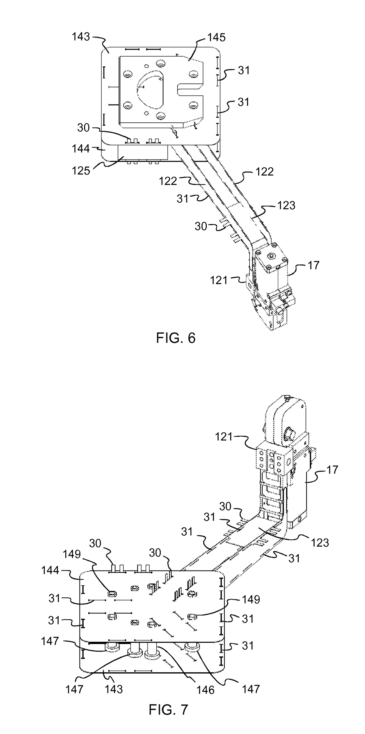
[0071]The single part 124 shown in FIG. 14 has a centering plug unit that comprises in FIG. 14 two straps 30, two noses 32 and a bar 33. The bar 33 is positioned herein between the both straps 30, that means at one of the sides of the straps. One of the noses 32 is positioned on the other side of one strap 30. The noses 32 and the bar 33 each project a little bit out of the edge of the single part 124 as illustrated by the broken lines in FIG. 14. In contrast thereto, the both straps 30 each project many times further out of the edge of the single part 124 than the noses 32. Preferably, the noses 32 and possibly also the bar 33 project out of the edge of the single part 124 so far that they can grip into one through opening 31 of another single part, one single part 122 in this case, however, that they do not project out of the through opening 31 in case the straps 30 are bent, as shown in FIG. 12 in the

[0072]The whole width of the straps 30, the noses 32 and the bars 33 at the edge...

third embodiment

[0074] the centering plug unit does not comprise a bar 33, as shown in FIG. 15. According to a first modification, only one strap 30 is existent herein, at which sides each is positioned one nose 32, as illustrated in FIG. 15 at the left edge of the single part 124. According to a second modification, in fact two straps 30 are existent at which sides each is positioned one nose, as illustrated in FIG. 15 at the right edge of the single part 124. However, the edge of the single part 124 does not project between the straps 30 but is located, for example, on the same straight line like the edge of the single part 124. Alternatively, the edge of the single part 124 located between the straps 30 can also be slotted out of the single part 124 in comparison to the other edge of the single part 124.

fourth embodiment

[0075] the centering plug unit does not comprise noses 32 as shown in FIG. 16 at the left edge of the single part 124. Alternatively, there can also be present only one nose 32 as shown in FIG. 16 at the right edge of the single part 124. In this case, the form-lock between the single parts 122 to 125, 143, 144 for the slip protection is formed by at least the straps 30 and possibly one nose 32.


PUM


Abstract

A device for use in handling a load and a method for producing the device are provided. The device comprises a three-dimensional framework that comprises a plurality of single parts, a cover made of a fiber-reinforced plastics with which the framework is covered, and at least one mounting unit for a handling unit for handling a part that is useable in the production of an object and that forms the load.

Description

CROSS-REFERENCE TO RELATED APPLICATIONS[0001]This application a 371 National Stage application of International Application No. PCT / EP2014 / 061541, filed on Jun. 4, 2014, which claims foreign priority based on European Patent application EP 13 171 149.1 filed on Jun. 7, 2013, both of which are incorporated herein by reference in their entireties.BACKGROUND OF THE INVENTION[0002]Field of the Invention[0003]The present invention relates to a device for use in handling a load and a method for producing such a device. In particular, the present invention relates to a device for use in handling a load and a method for producing such a device which can be used in a production plant. The production plant is in particular an assembly line for a vessel.[0004]Description of the Prior Art[0005]In production plants for industrially produced objects, like for example cars, media apparatuses, furniture, etc., single components of the object which is to be produced are usually moved from one place ...

Claims


Application Information

Patent Timeline
Patent Type & Authority Patents(United States)
IPC IPC(8): B25J19/00B25J11/00B25J9/00B25J15/00B25J15/06
CPCB25J15/00B25J9/0012B25J19/007B25J15/0052B25J15/0616B25J11/00
Inventor KRAFT, MARTINSCHNEEGANS, JOCHEN
Owner FFT PRODIONSSYST
Why Eureka
Try Eureka