Blow molding machine with internal tempering device

a technology of internal tempering and blow molding machine, which is applied in the field of blow molding machine, can solve the problems of performance loss, inability to meet the needs of domestic applications, and inability to meet the needs of domestic applications, and achieve the effect of reducing the efficiency of the blow molding machine, and reducing the cost of re-heating or cooling

Active Publication Date: 2019-01-08
KRONES AG
View PDF16 Cites 1 Cited by
  • Summary
  • Abstract
  • Description
  • Claims
  • Application Information

AI Technical Summary

Benefits of technology

[0003]The invention is characterized in that the blow molding machine, comprising a stationary and a rotating part with blow molds as well as a tempering device for tempering the blow molds, is characterized in that the tempering device is disposed within the blow molding machine. This firstly achieves significant space-saving, since, for example, no lines are necessary outside the blow molding machine for transporting the cooling liquid from the tempering device to the individual blow molds. Secondly, due to the arrangement of the tempering device immediately within the blow molding machine, any change of temperature of the medium during the transport to the blow mold can be effectively reduced or even avoided. As a result, costly insulation of the respective lines and intermediate stations for re-heating or cooling can be partially or completely obsolete.
[0011]In another embodiment, the cold water is added in dependency of the temperature of the blow mold. This allows specific control of cold water addition, and stabilization of the target temperature is adjusted to the current processes in the blow molding machine.

Problems solved by technology

However, this requires a certain amount of space and leads to performance losses during transport of the cooling liquid.
As a result, costly insulation of the respective lines and intermediate stations for re-heating or cooling can be partially or completely obsolete.
Avoiding the formation of condensate can significantly improve the lifetime of the blow molding machine, as, for example, rust or other material damage due to condensation on connection pipes can impair the operativeness of the blow molding machine.
Furthermore, contamination by microorganisms is made more difficult because the necessary moisture on the surfaces is lacking.

Method used


Image

  • Blow molding machine with internal tempering device

Examples


Embodiment Construction

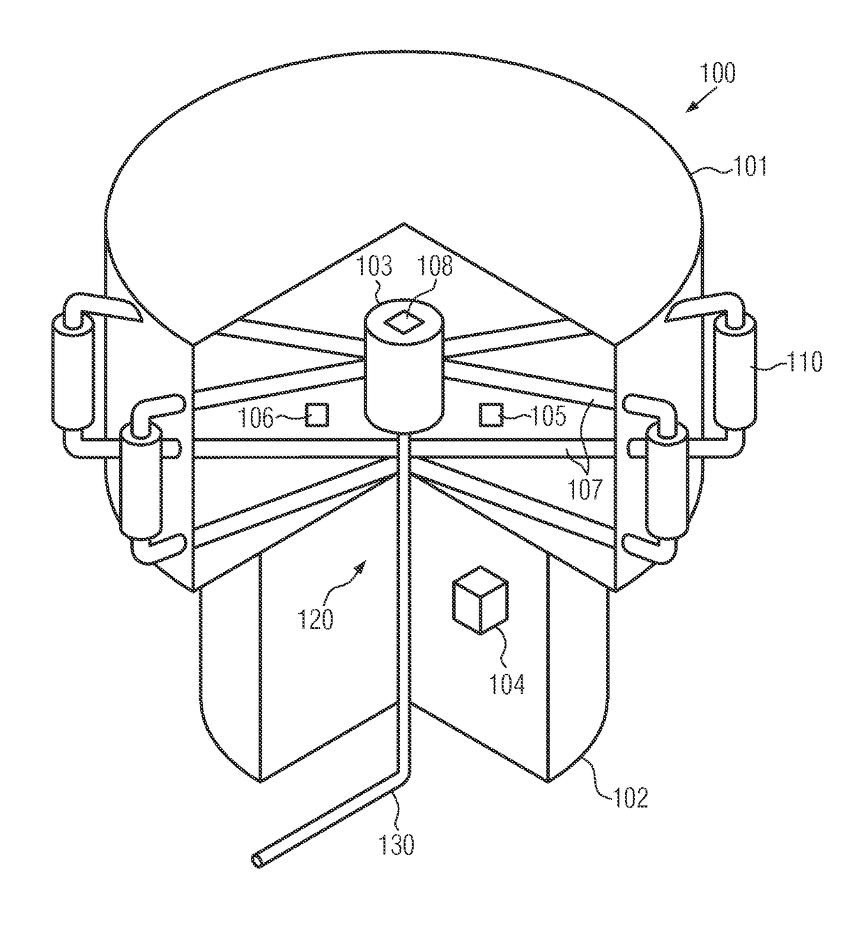
[0013]FIG. 1 illustrates a blow molding machine 100 according to the invention. It comprises a stationary part 102 and a rotating part 101. The blow molds 110 are arranged on the rotating part 101 of the blow molding machine 100. During the blow molding process, it is firstly necessary to temper the forms so that the introduced plastic can assume a corresponding shape and characteristics. On the other hand, it is thereafter necessary to cool the blow forms as quickly as possible, so that, for example, a change of molds can be performed. To ensure this, a tempering device 120 is provided. According to the invention, it can be arranged within both the stationary as well as the rotating part of the blow molding machine 102 or 101, respectively. It comprises a cooling water supply 103 which can be connected via a supply line 130 to an external water supply. Furthermore, heating and cooling elements 105 and 106, respectively, are provided. They are used for heating or cooling the medium,...


PUM

PropertyMeasurementUnit
temperatureaaaaaaaaaa
distanceaaaaaaaaaa
flexibleaaaaaaaaaa

Abstract

A blow molding machine with a stationary and a rotating part, comprising a tempering device for tempering blow molds of the blow molding machine using a medium, and a respective method, characterized in that the tempering device is arranged within the blow molding machine.

Description

BACKGROUND OF THE INVENTION[0001]The invention relates to a blow molding machine with a tempering device and a respective method for tempering blow molds and their mounting fixtures (mold carrier) of a blow molding machine.SUMMARY OF THE INVENTION[0002]Blow molding machines are known from prior art. As in particular the blow molds must be cooled and the preforms must be heated, the use of heating stations and cooling elements in connection with blow molding machines is known e.g. from DE 20 309 576 U1. It discloses a blow molding machine for producing hollow bodies of thermoplastic material, where a heating station is provided for heating the preforms and cooling means for cooling the blow mold. The coolant is provided by a cooling unit, which relative to the dimensions of the blow machine is arranged at a greater distance from the blow molding machine. However, this requires a certain amount of space and leads to performance losses during transport of the cooling liquid.[0003]The i...

Claims


Application Information

Patent Timeline
Patent Type & Authority Patents(United States)
IPC IPC(8): B29C49/36B29D22/00B29C49/64
CPCB29D22/003B29C49/64B29C49/36
Inventor HOLLRIEGL, THOMASBRUNNER, ANDREAS
Owner KRONES AG
Why Eureka
Try Eureka