Compact electro-hydraulic generator to motorise cupola

a compact, electro-hydraulic technology, applied in the direction of rotary clutches, couplings, fluid couplings, etc., can solve the problems of large speed overrun, insufficient mechanical characteristics of such a motor, and very intermittent profile of use of turrets or cupolas, etc., to achieve substantial space saving, easy handling, and the effect of expanding the volum

Inactive Publication Date: 2006-05-11
NEXTER SYST SA
View PDF12 Cites 2 Cited by
  • Summary
  • Abstract
  • Description
  • Claims
  • Application Information

AI Technical Summary

Benefits of technology

[0028] Another advantage of the device according to the present invention lies in its cylindrical shape which extends the volume occupied by the cupola head.
[0029] Another advantage of the device according to the present invention lies in the fastening of all the components on the tank. An easily handled single unit is thus obtained that can be installed into its housing in a single operation.
[0030] Another advantage of the device according to the present invention is to allow the use of a single hydraulic generator to supply several cupolas installed, for example, on the same fixed equipment or vehicle. This affords, in addition to the economic advantages, a substantial saving of space.
[0031] Another advantage of the device according to the present invention is to allow a close cupola head assembly to be installed directly above the generator and / or one or several cupola head assemblies offset at a distance.
[0032] Another advantage of the device according to the present invention obtained when a cupola head is offset is to substantially reduced the height of the cupola above the fixed equipment or vehicle with the advantages of reduced detectability that result from this.
[0033] Another advantage of the device according to the present invention lies in the use of linking means that may be flexible or rigid piping thereby offering the possibility of offsetting the hydraulic generator and allowing great architectural flexibility since the generator does not necessarily have to be housed under the head assembly.

Problems solved by technology

The mechanical characteristics of such a motor are generally not enough in terms of torque and are oversized in terms of speed.
However, the profile of use of a turret or cupola motorisation is very intermittent.
The back-geared electric motor is not well adapted to such profiles of demand for power.
However, in spite of its great specific output allowing a substantial power supply, the relatively large number of necessary components discourages the expert when he has to design a compact architecture compatible with the limited space in the equipment.

Method used


Image

  • Compact electro-hydraulic generator to motorise cupola
  • Compact electro-hydraulic generator to motorise cupola
  • Compact electro-hydraulic generator to motorise cupola

Examples


Embodiment Construction

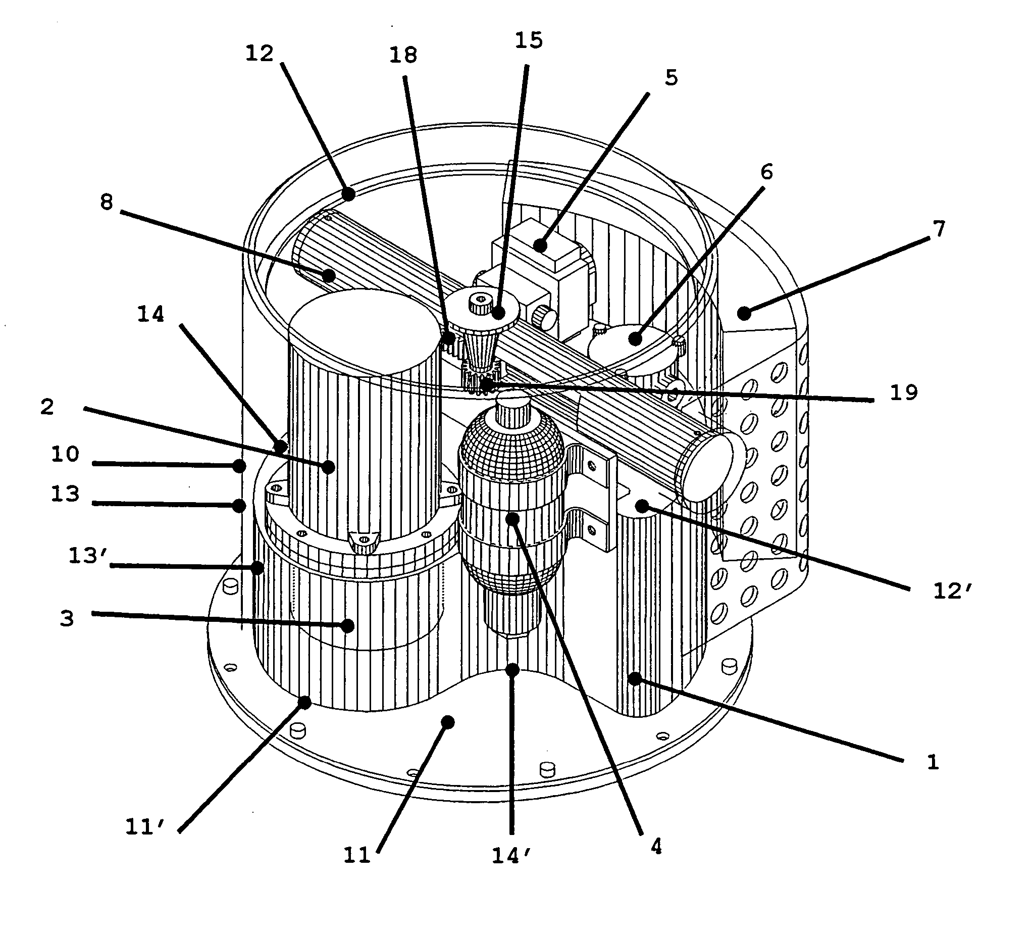
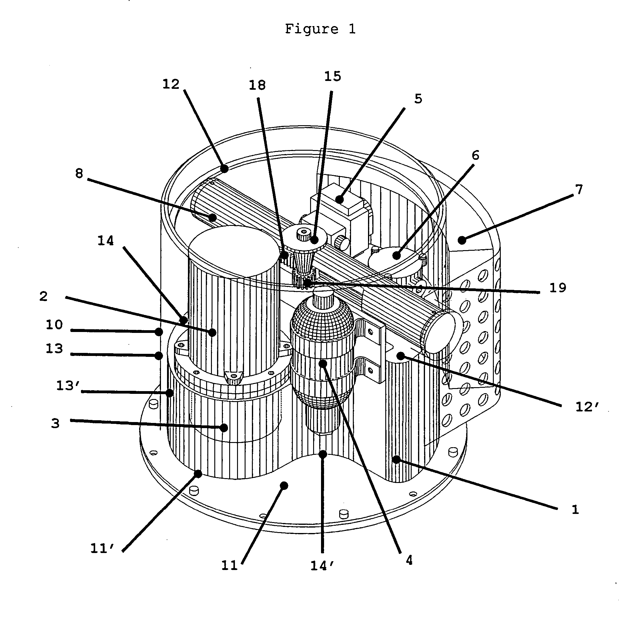
[0039] In FIG. 1, the electro-hydraulic generator comprises the following components: a tank or cistern of hydraulic fluid 1, a motor 2, a pump 3 housed inside the tank 1, facing the motor 2, an accumulator 4, distribution means 5, a filter 6, an exchanger 7, and actuator 8. The linking means 9 are not shown in the Figure. They are situated either outside or inside the tank 1 and connect components 2, 3, 4, 5, 6, 7, 8 and the tank 1 to form a circuit.

[0040] The hydraulic generator occupies a cylindrical volume 10. This first cylinder is delimited sidewards by a circular surface 13, downwards by a plane end surface 11 and upwards by a plane end surface 12.

[0041] In FIG. 1, the hydraulic generator is shown installed in a cylindrical case. The inside of the cylindrical case delimits this first cylinder 10, 11, 12, 13. In the configuration where the head assembly is shown close, this case ensures the protection of the hydraulic generator as well as the support of the cupola head assem...


PUM


Abstract

The present invention divulges a particularly compact electro-hydraulic generating set and its application in combination with a compact actuator to pilot the traverse movement of a close cupola head assembly or of one or several offset cupola head assemblies. The compactness of the electro-hydraulic generating set and the possibility of the close or offset mounting of one or several cupola head assemblies make various architectures possible.

Description

BACKGROUND OF THE INVENTION [0001] The technical scope of the present invention is that of electro-hydraulic generating sets or rotating actuating gear used to rotate the turrets or cupolas, for example of weapon systems. [0002] To date, hydraulic motorisations to drive turrets or cupolas in rotation are known. Such actuating gear have been frequently used in dated equipment or weapon systems and notably in vehicles that had a hydraulic generating set on board, already installed for other functions, for example propulsion. In these cases, the actuating gear amounted to no more than a hydraulic motor, the hydraulic power being supplied by the equipment's central hydraulic generating set. [0003] The current trend is to gradually replace hydraulic generating systems by electric generating systems to supply equipment and notably vehicles. This naturally leads to the use of motorisations to drive the turrets or cupolas, of a type adapted to the power available on the equipment, in other ...

Claims


Application Information

Patent Timeline
Patent Type & Authority Applications(United States)
IPC IPC(8): F16D31/00F15B1/26F41A27/20F41A27/26
CPCF15B1/26F41A27/20F41A27/26
Inventor PECOUYOUL, GABRIEL
Owner NEXTER SYST SA
Why Eureka
Try Eureka