Supercharge Your Innovation With Domain-Expert AI Agents!

Clamping mechanism and gimbal having the clamping mechanism

a technology of gimbal and clamping mechanism, which is applied in the field of photography equipment, can solve the problems of inconvenient manipulation of prior art phone holder and likely release of phone device from the phone holder, and achieve the effect of providing rotation resistance and facilitating manipulation of the clamping mechanism

Inactive Publication Date: 2019-01-08
SZ DJI TECH CO LTD
View PDF22 Cites 6 Cited by
  • Summary
  • Abstract
  • Description
  • Claims
  • Application Information

AI Technical Summary

Benefits of technology

[0005]An aspect of the disclosure provides a clamping mechanism comprising a holding portion and an adaptor connected to the holding portion, the adaptor connecting the clamping mechanism to a bearing member. The holding portion can be rotatably connected to the adaptor to adjust an attitude relative to the adaptor. The clamping mechanism can further comprise a damping member disposed between the holding portion and the adaptor. The damping member can provide a rotational resistance when the holding portion rotates with respect to the adaptor, such that the holding portion can be retained at an attitude relative to the adaptor by the rotational resistance when an external force rotating the holding portion is removed. The adaptor can comprise a connecting member through which the adaptor can be connected to the bearing member.
[0041]With the clamping mechanism and the gimbal having the clamping mechanism of the disclosure, the holding portion can be rotatably connected to the adaptor to adjust an attitude of the holding portion with respect to the adaptor. In some instances, the clamping mechanism can comprise a damping member provided between the holding portion and the adaptor. The damping member can provide a rotational resistance when the holding portion rotates relative to the adaptor. The holding portion can be retained at a desire attitude with respect to the adaptor by the rotational resistance when an external force rotating the holding portion is removed. An attitude of an object clamped by the clamping mechanism can be varied by simply rotating the clamping mechanism. A manipulation of the clamping mechanism can be made easy.

Problems solved by technology

However, the phone device is likely to release from the phone holder due to a shock.
The manipulation of prior art phone holder is inconvenient.

Method used


Image

  • Clamping mechanism and gimbal having the clamping mechanism
  • Clamping mechanism and gimbal having the clamping mechanism
  • Clamping mechanism and gimbal having the clamping mechanism

Examples


first embodiment

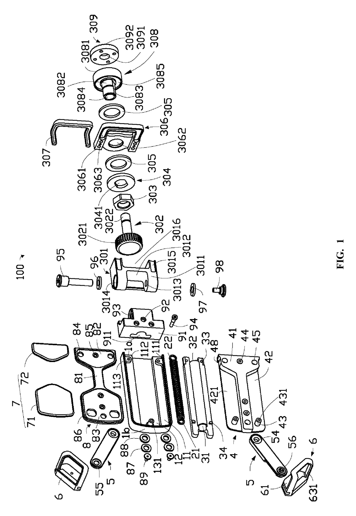
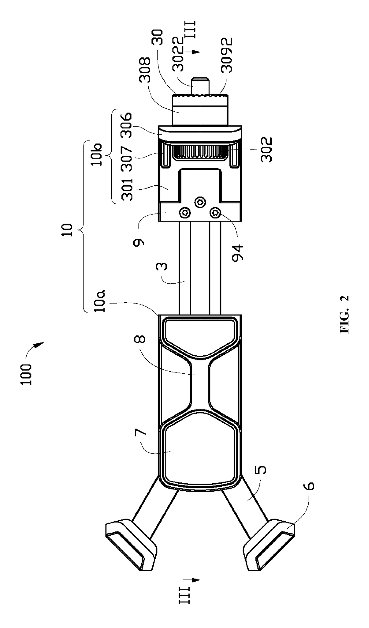
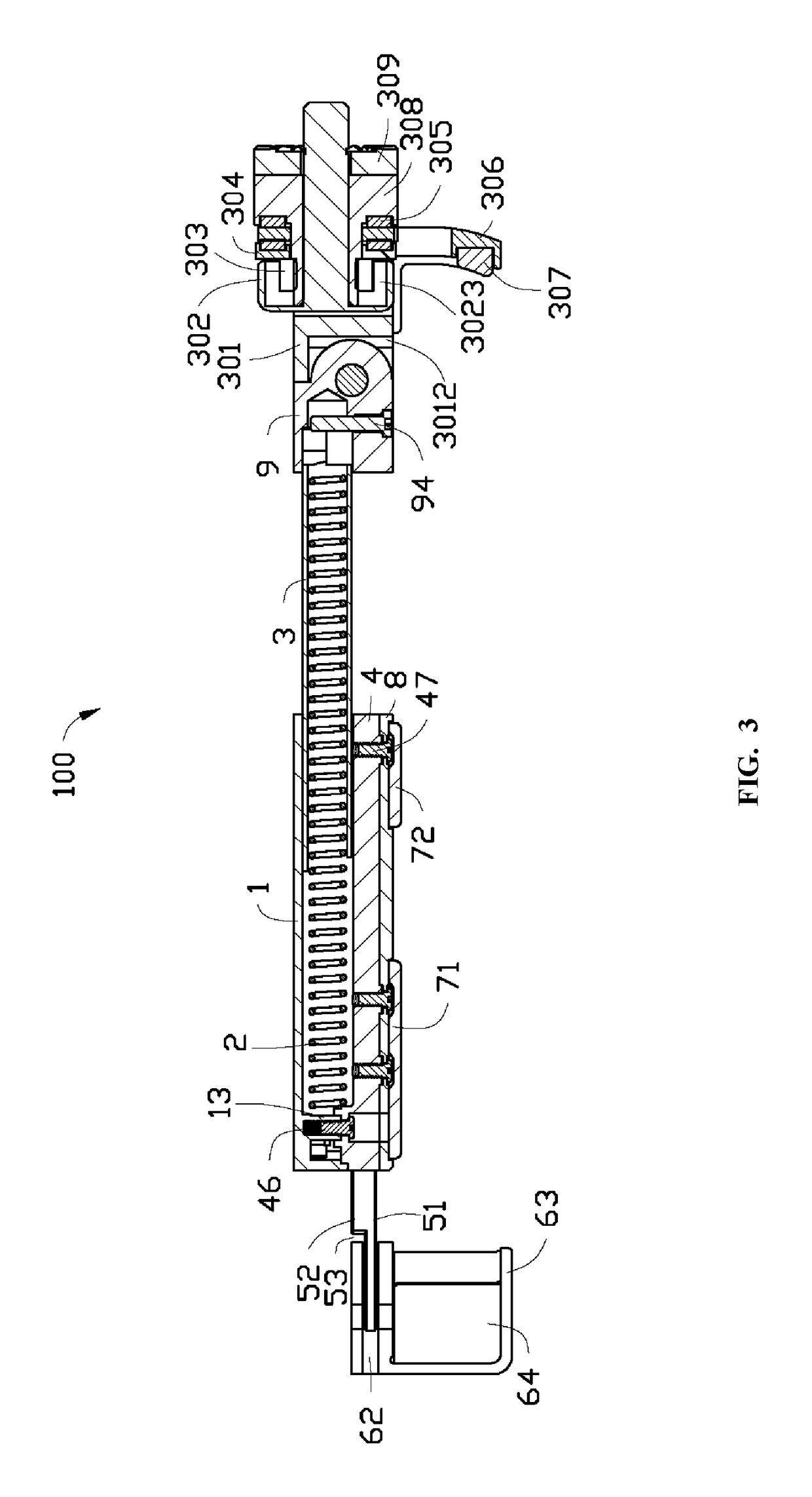
[0055]Referring to FIGS. 1 to 3, the present disclosure provides a clamping mechanism 100 comprising a holding portion 10, an adaptor 30 connected to the holding portion 10 and a damping member 305 disposed between the holding portion 10 and the adaptor 30.

[0056]The holding portion 10 can comprise a first clamping member 10a and a second clamping member 10b rotatably connected to the first clamping member 10a. The first clamping member 10a can comprise a bottom casing 1, a tension spring 2, a guiding member 3, a base plate 4, an arm 5, a clamp 6, a first elastic member 7, a bearing plate 8 and a pivoting portion 9.

[0057]The bottom casing 1 can comprise a first end 1a and a second end 1b which is provided opposite to the first end 1a. The bottom casing 1 can be provided with a first groove 11. The first groove 11 can comprise two first sides 111 which are provided opposite to each other. In some instances, the bottom casing 1 can comprise a connecting block 112 for connecting with th...

second embodiment

[0082]FIG. 4 shows a gimbal 200 according to the disclosure. The gimbal 200 can comprise a main body 201 and the clamping mechanism 100 as discussed hereinabove. The clamping mechanism 100 can be connected to the main body 201. The main body 201 can be the bearing member as discussed hereinabove. The threaded shaft 3022 of the connecting member 302 of the clamping mechanism 100 can be threadedly connected to the main body 201. The main body 201 can comprise an engaging portion 2011 abutting against the tightening portion 3092 of the chuck 309 of the clamping mechanism 100, such that the chuck 309 can be connected to the main body 201. In some embodiments, the engaging portion 2011 can be a teethed plate.

[0083]Referring to FIG. 5, when an object (not shown) is clamped by the gimbal 200, a first end of the object can abut against the second elastic member 307 of the clamping mechanism 100. The holding portion 10 can be pulled to adjust a distance between the second elastic member 307 ...


PUM


Abstract

A gimbal includes a main body and a clamping mechanism rotatably connected to the main body. The clamping mechanism includes an adaptor connecting the clamping mechanism to the main body. The adaptor includes a connecting member connecting the adaptor to the main body. The clamping mechanism further includes a holding portion rotatably connected to the adaptor and one or more damping members disposed between the holding portion and the adaptor. The one or more damping members are configured to provide a resistance to a rotation of the holding portion with respect to the adaptor.

Description

CROSS-REFERENCE TO RELATED APPLICATION[0001]This application is a continuation application of International Application No. PCT / CN2015 / 086541 filed Aug. 10, 2015, the entire contents of which are incorporated herein by reference.TECHNICAL FIELD[0002]The disclosure relates to a photographic equipment, and particularly to a clamping mechanism and a gimbal having the clamping mechanism.BACKGROUND OF THE DISCLOSURE[0003]Prior art phone holders can hold a phone device by clamping opposite sides of the phone. However, the phone device is likely to release from the phone holder due to a shock. Some phone holders can hold the phone device by clamping four sides of the phone. However, a user has to manipulate an object, to which the phone holder is attached, to adjust an attitude of the phone. The manipulation of prior art phone holder is inconvenient.SUMMARY OF THE DISCLOSURE[0004]There is a need for a clamping mechanism capable of easily adjusting an attitude and a gimbal having the clampi...

Claims


Application Information

Patent Timeline
Patent Type & Authority Patents(United States)
IPC IPC(8): F16M13/04F16M11/04F16M11/20H04M1/02G03B17/56B25J1/00B25J15/00F16M11/10
CPCF16M13/04B25J1/00B25J15/0028F16M11/04F16M11/10F16M11/2028G03B17/56G03B17/561H04M1/0264F16M11/2014G03B17/563G03B17/566F16M11/041F16M11/18F16M2200/041
Inventor ZHAO, XIFENGLIU, GUOYAO
Owner SZ DJI TECH CO LTD
Features
  • R&D
  • Intellectual Property
  • Life Sciences
  • Materials
  • Tech Scout
  • Unparalleled Data Quality
  • Higher Quality Content
  • 60% Fewer Hallucinations
Learn More