Twist fitting for air tank connections

Inactive Publication Date: 2005-09-13
Q3JMC
View PDF20 Cites 42 Cited by
  • Summary
  • Abstract
  • Description
  • Claims
  • Application Information

AI Technical Summary

Benefits of technology

[0007]The locking members are further formed with catch elements extending parallel to a longitudinal axis of the bushing body and located in spaced relat

Problems solved by technology

Accordingly, production of the tank requires attention to proper formation of the weld conn

Method used


Image

  • Twist fitting for air tank connections
  • Twist fitting for air tank connections
  • Twist fitting for air tank connections

Examples


Embodiment Construction

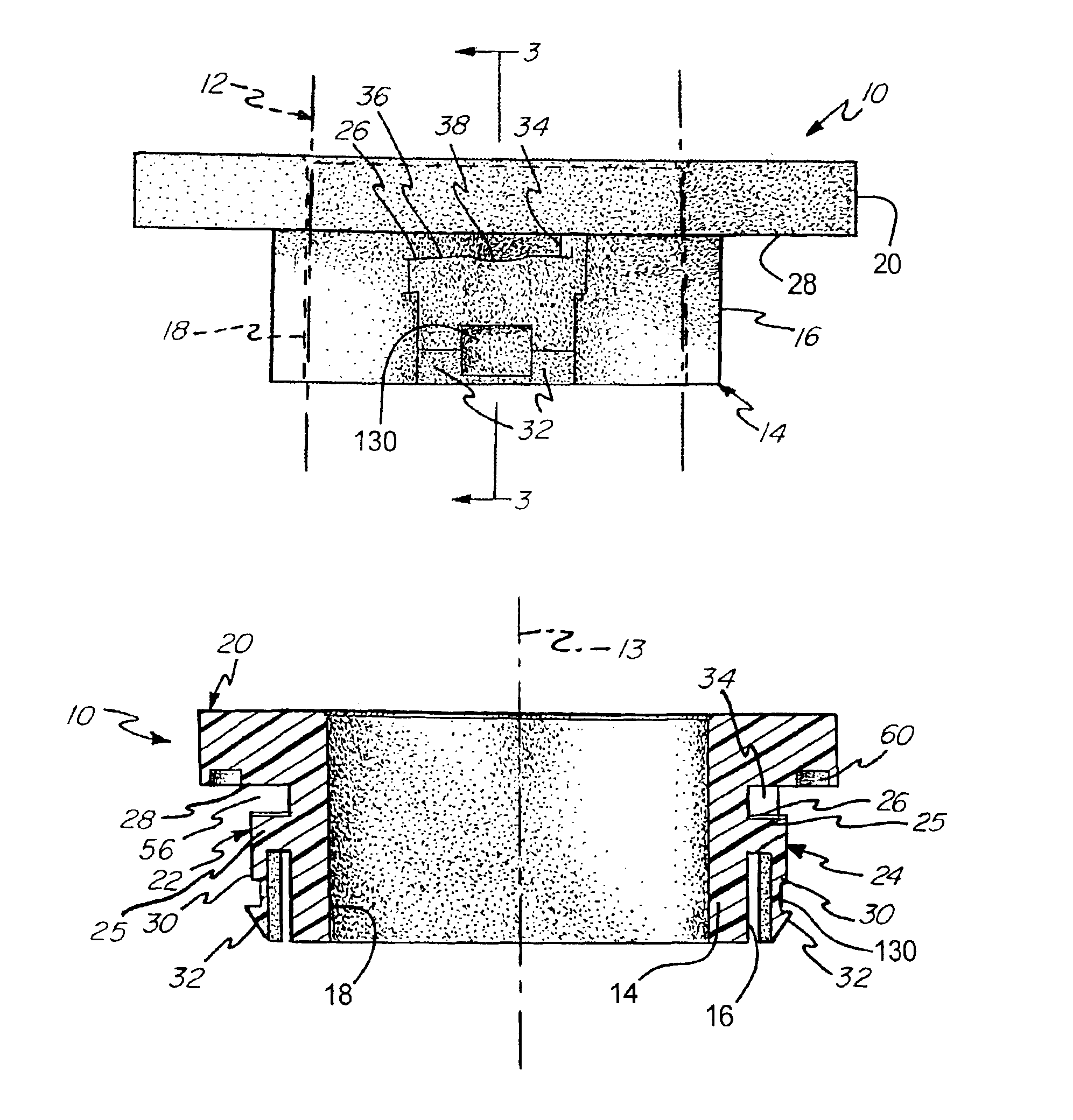
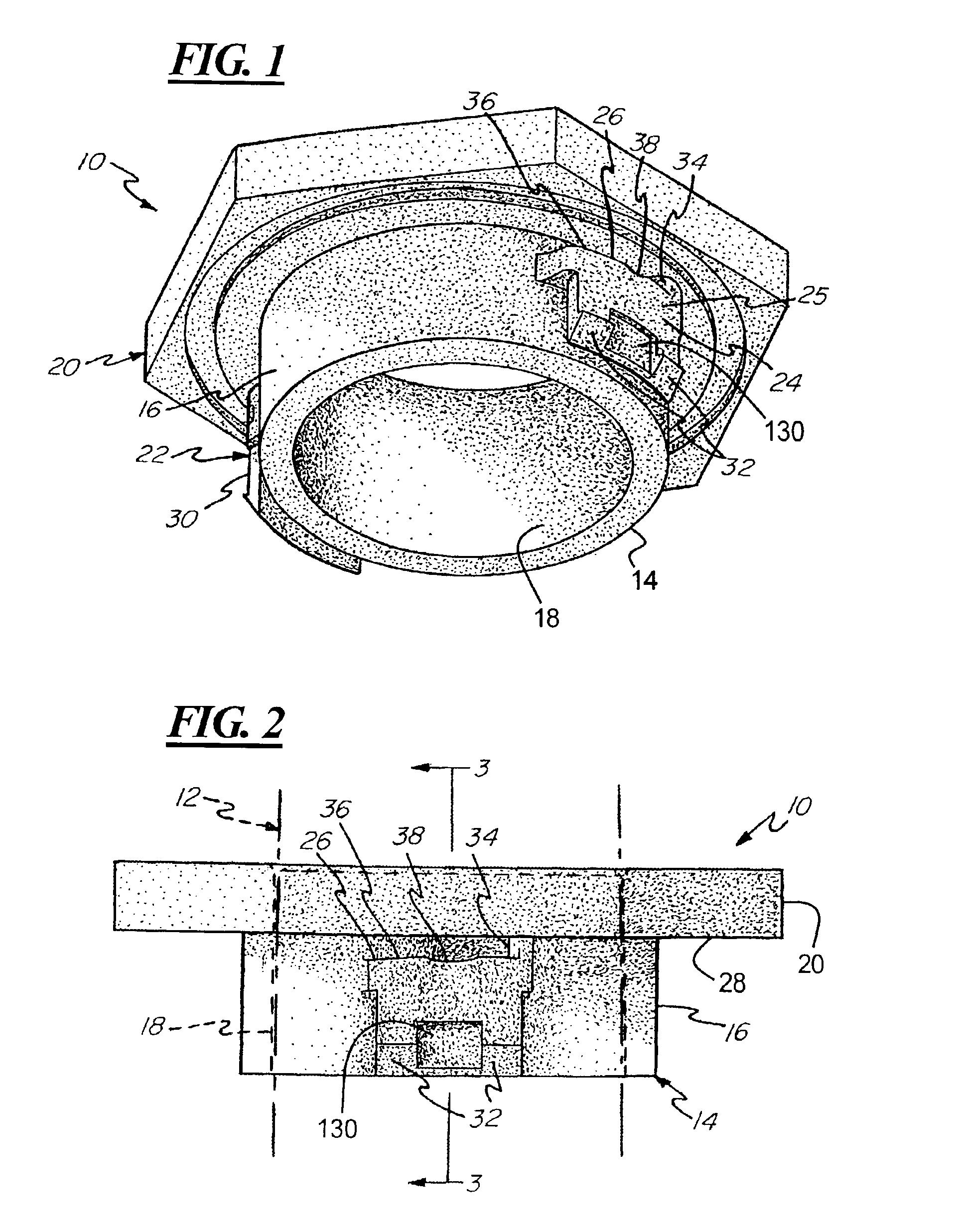
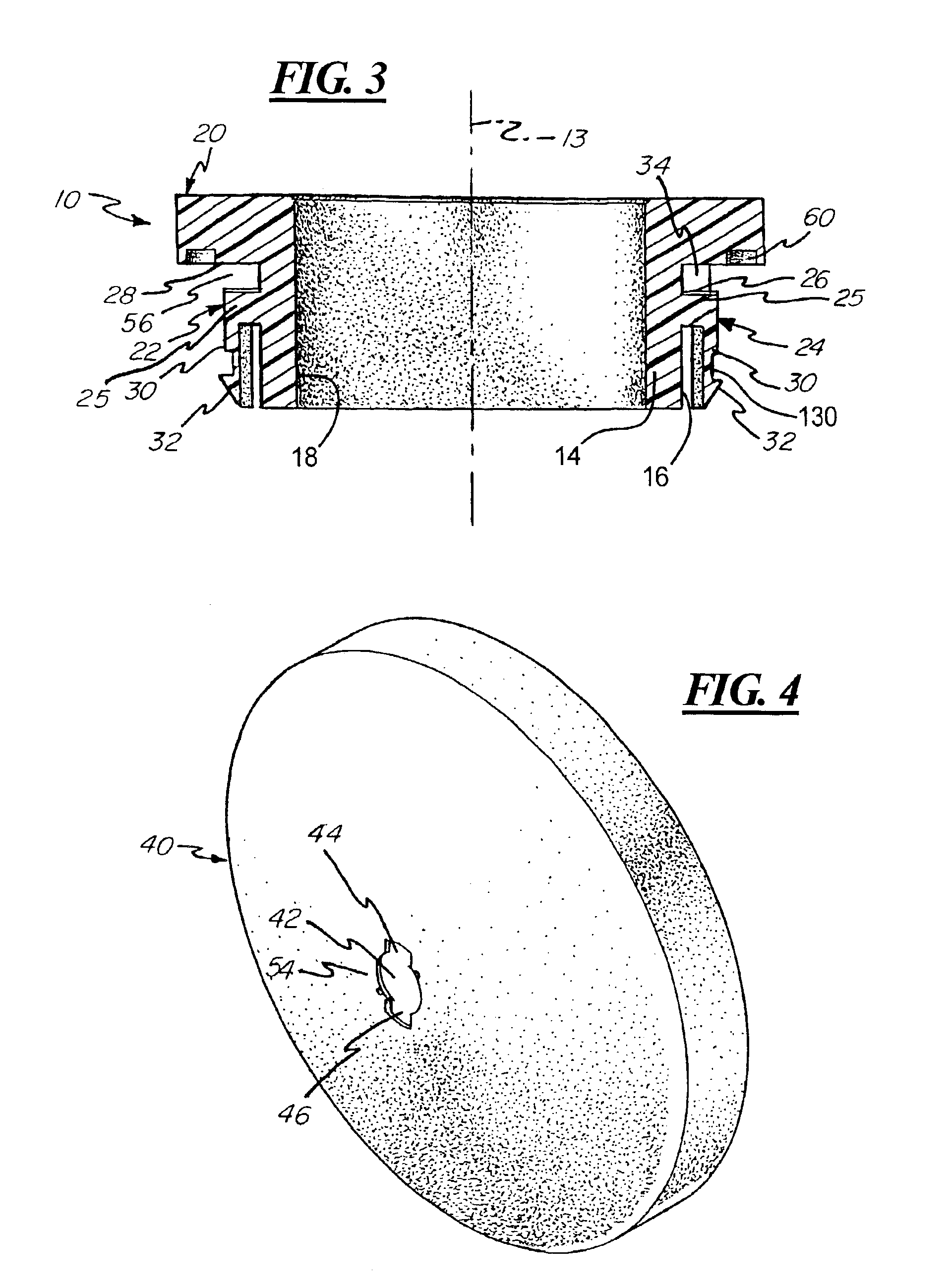
[0021]Referring to FIGS. 1-3, the fitting structure of the present invention includes a bushing 10 for mounting to the wall of a tank and for supporting a fitting, illustrated diagrammatically as 12. The bushing includes a cylindrical body 14 defined by a cylindrical outer surface 16 and a cylindrical inner surface 18 wherein the cylindrical inner surface 18 defines a cylindrical aperture through the bushing 10.

[0022]A head portion 20 is formed integrally with and extends radially outwardly from the cylindrical body 14. The head portion 20 defines a tool-engaging portion of the bushing 10 and in the illustrated embodiment is provided with a hexagonal shape for engagement with a wrench.

[0023]A pair of locking members 22, 24 are located on diametrically opposite sides of the cylindrical body 14. Each locking member 22, 24 includes a base portion 25 extending radially from the outer surface 16 of the cylindrical body 14 and includes an upper surface 26 facing toward a lower surface 28 ...


PUM


Abstract

A fitting connector for a pressure vessel including a bushing for mounting within an aperture defined in a pressure vessel wall. The bushing includes a cylindrical bushing body having a head portion at one end thereof and including at least a pair of locking members for engaging along an interior surface of the pressure vessel wall. The locking members are provided with a contoured surface for engaging with detent members formed on the interior of the pressure vessel wall whereby the bushing is positively locked in a predetermined rotational orientation on the pressure vessel wall and is retained in place until a predetermined torque force is applied.

Description

REFERENCE TO PROVISIONAL APPLICATION[0001]This application claims benefit of the filing date of U.S. Provisional Application No. 60 / 374,731 filed Apr. 23, 2002.BACKGROUND OF THE INVENTION[0002]The present invention relates to a fitting for use with air tanks and, more particularly, to a fitting including a twist end bushing for interfacing with an opening in an air tank.[0003]Air tanks are typically provided with fittings for connection to tubing or other passageways leading to the air tank. In the past, such fittings have been attached to the air tank by means of a bushing welded to an aperture formed through the wall of the tank. Accordingly, production of the tank requires attention to proper formation of the weld connection and a corresponding labor and manufacturing time cost associated with this operation.[0004]Accordingly, there is a need for a fitting structure for use with air tanks wherein the fitting structure is easily assembled to the tank. In addition, there is a need ...

Claims


Application Information

Patent Timeline
IPC IPC(8): F16L37/00F16L37/252
CPCF16L37/252F16L37/008
Inventor PICKERING, RICHARD CARLTON
Owner Q3JMC
Why Eureka
Try Eureka